CAN Bus Explained - A Simple Intro [2026]
Need a simple, practical intro to CAN bus?
In this tutorial we explain the Controller Area Network (CAN bus) for beginners, incl. the CAN frame, higher-layer protocols and how to log/decode CAN bus data.
Read on to learn why this has become the #1 guide on CAN bus.
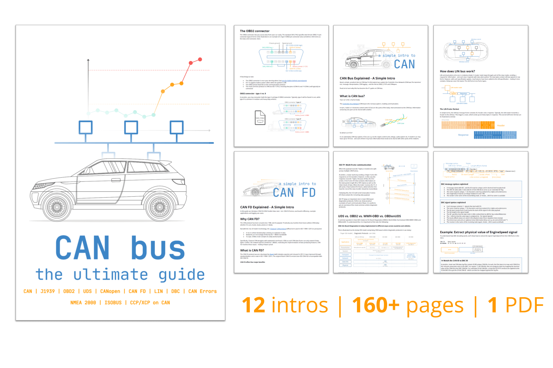
You can also view our CAN bus protocol intro above or get the PDF.
In this article

What is CAN bus?
CAN bus (Controller Area Network) is a communication system used in vehicles/machines to enable ECUs (Electronic Control Units) to communicate with each other - without a host computer. For example, the CAN bus enables quick and reliable sharing of information between your car's brakes and engine.
Let's imagine your car is like the human body:
The CAN bus is the nervous system, enabling communication.
In turn, ECUs (aka 'CAN nodes') are like parts of the body, interconnected via the CAN bus. Information sensed by one part can be shared with another.
In physical terms, all ECUs are connected on a two-wire bus consisting of a twisted pair: CAN high and CAN low. The wires are often color coded: CAN high is yellow (like the sun), CAN low is green (like the grass).


What is an ECU?
Electronic Control Units (ECUs) are components that control certain functionality - e.g. the engine control unit, transmission, brakes, steering, temperatures etc. A modern car can easily have 70+ ECUs - each sharing information with other ECUs on the bus.
Any ECU on the CAN bus can prepare and broadcast information (e.g. sensor data). The broadcast data is accepted by all other ECUs on the network - and each ECU can then check the data and decide whether to receive or ignore it.
If we zoom in, an ECU consists of three primary elements:
- Microcontroller: The MCU is the brain of the ECU - it interprets incoming CAN messages and decides what messages to transmit. For example, a sensor might be programmed to measure and broadcast oil temperature at 5 Hz
- CAN controller: The controller is typically integrated in the MCU and ensures all communication adheres to the CAN protocol (message encoding, error detection, arbitration etc.) - removing complexity from the MCU
- CAN transceiver: The CAN transceiver connects the CAN controller to the physical CAN wires, converting controller data into differential signals for the CAN bus system and vice versa. It also provides electrical protection


CAN bus DB9 connector
How do you connect to a CAN bus?
There is no standard connector across CAN bus applications. As we show later, this implies that different vehicles/machines may use different connectors.
However, a close candidate is the CAN DB9 (D-sub9) connector (CANopen CiA 303-1), which has become the de facto standard for many applications including CAN bus data loggers/interfaces.
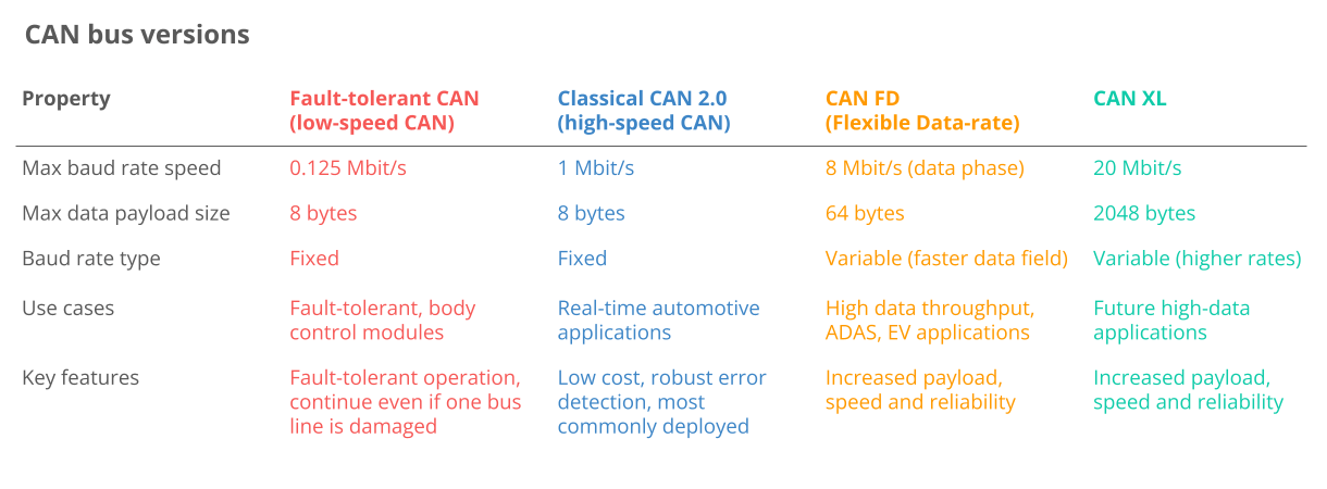
CAN bus variants
Before we proceed, it is useful to know that multiple variants of CAN exist:
- Low-speed CAN: Fault-tolerant CAN is a low cost option when fault tolerance is critical - but is increasingly replaced by LIN bus
- High-speed CAN: Classical CAN is the most common variant today across automotives/machinery (and the focus of this article)
- CAN FD: Offers longer payloads and faster speed, though adoption remains limited - learn more in our CAN FD intro
- CAN XL: Offers even longer payloads and faster speed to bridge the gap between CAN and Automotive Ethernet (100BASE-T1)
In automotives you'll often encounter other non-CAN networks - below are the most relevant:
- LIN bus: LIN bus is a lower cost supplement to CANbus networks, with less harness and cheaper nodes. LIN bus clusters typically consist of a LIN master acting as gateway and up to 16 slave nodes. Typical use cases include e.g. non-critical vehicle functions like aircondition, door functionality etc. - for details see our LIN bus intro or LIN bus data logger article
- FlexRay: FlexRay offers higher speed than CAN (up to 10 Mbit/s), fault-tolerance through its dual-channel redundancy and high flexibility - but is also more costly. It is standardized as per ISO 17458-1 and ISO 17458-5
- Automotive Ethernet: This is increasingly being rolled out in the automotive sector to support the high bandwidth requirements of ADAS (Advanced Driver Assistance Systems), infotainment systems, cameras etc. Automotive Ethernet offers much higher data transfer rates vs. CAN bus, but lacks some of the safety/performance features of CAN. Most likely, the coming years will see both Automotive Ethernet, CAN FD and CAN XL being used in new automotive and industrial development
Top 4 benefits of CAN bus
The CAN bus standard is used in practically all vehicles and many machines due to below key benefits:

Simple & low cost
ECUs communicate via a single CAN system instead of via direct complex analogue signal lines - reducing errors, weight, wiring and costs
- Reduced wire complexity: Traditional point-to-point wiring systems would require dedicated wires between each related node, making the system costly and inflexible - a good example being NMEA 0183 vs. NMEA 2000
- Weight reduction: Switching to CAN bus can help reduce the weight of a vehicle's wiring harness by up to 20 kg, reducing e.g. fuel costs
- Scale: The immense popularity of CAN is itself a factor that reduces the cost of everything from controllers, transceivers, harnesses - and more indirectly related costs like data acquisition hardware, training etc.

Easy access
The CAN bus provides 'one point-of-entry' to communicate with all network ECUs - enabling central diagnostics, data logging and configuration
- Centralized diagnostics: By design, CAN bus lets you connect an interface anywhere on the CAN bus to gain direct access to 100% of the traffic. This greatly simplifies diagnostics as you avoid the need to collect data individually for each node
- Silent CAN logging: In particular, CAN bus data logging can be performed in 'silent mode', ensuring that the device does not affect the CAN bus at all - critical for e.g. diagnostics
- ECU flashing: You can also update any ECU on the network via the CAN bus by transmitting firmware/config updates as CAN frames. Typically this is done using higher-layer protocols like UDS or CCP/XCP
- Standardization: Most CAN applications today also share higher-layer protocols that are standardized across manufacturers and brands (more on these below) - enhancing the interoperability of e.g. hardware/software tools

Extremely robust
The system is robust towards electric disturbances and electromagnetic interference - ideal for safety critical applications (e.g. vehicles)
- Differential signaling: Electromagnetic interference (EMI) affects both lines in the CAN bus two-wire system equally, making the differential signal robust against this form of environmental noise
- Error handling: CAN ensures data integrity through extensive error detection, incl. CAN errors like bit errors, stuff errors, CRC errors, form errors and ACK errors). Further, nodes can be setup to automatically retransmit faulty messages
- Confinement: In addition, CAN nodes are designed to track their own errors and to temporarily/permanently disconnect from the bus if it exceeds certain thresholds (aka 'bus off')

Efficient
CAN frames are prioritized by ID so that top priority data gets immediate bus access, without causing interruption of other frames or CAN errors
- Arbitration: When multiple CAN nodes attempt to transmit data in parallel, the frame with the lowest CAN ID (highest priority) wins, while the rest back off and retry. This avoids collisions and ensures that safety-critical messages are prioritized
- Utilization: Arbitration also helps ensure the CAN bus bandwidth is well-utilized, effectively 'filling gaps' between critical messages with lower priority messages
- Speed: While Classical CAN is 'slow' in comparison to e.g. automotive ethernet, it still offers sufficient speed for most automotive/industrial applications today. A single 1 Mbit/s CAN bus enables communication of thousands of CAN frames/second
The CAN bus history in short
- Pre CAN: Car ECUs relied on complex point-to-point wiring
- 1986: Bosch developed the CAN protocol as a solution
- 1991: Bosch published CAN 2.0 (CAN 2.0A: 11 bit, 2.0B: 29 bit)
- 1993: CAN is adopted as international standard (ISO 11898)
- 2003: ISO 11898 becomes a standard series
- 2012: Bosch released the CAN FD 1.0 (flexible data rate)
- 2015: The CAN FD protocol is standardized (ISO 11898-1)
- 2016: The physical CAN layer for data-rates up to 5 Mbit/s standardized in ISO 11898-2 (in practice up to 8 Mbit/s)
- 2018: CiA starts development of CAN XL
- 2024: CAN XL standardized (ISO 11898-1:2024, 11898-2:2024)
Today, CAN is standard in automotives (cars, trucks, buses, tractors, ...), ships, planes, EV batteries, machinery and more.


The future of CAN bus
Looking ahead, the CAN bus protocol will stay relevant - though it will be impacted by major trends:
- Need for speed: Demand for higher data rates may drive transition towards CAN FD, CAN XL or Automotive Ethernet
- Connected vehicles: Rise of cloud computing and vehicle telematics may enable e.g. predictive maintenance and remote troubleshooting/updates - but also cybersecurity risks
- Open vs. closed: A push towards 'Open Source' and Right to Repair may face off vs. an OEM-driven demand for keeping data proprietary to e.g. offer subscription-based microservices
It should be noted that the transition from Classical CAN towards e.g. CAN FD, CAN XL or Automotive Ethernet is in practice going to be slow. In our own experience across 10,000+ customers, less than 0.1% of use cases involve CAN FD as of 2024 and 0% involve CAN XL (which is not yet deployed in the field as of 2024).
CAN FD was touted as a clear successor to Classical CAN back in 2016 by e.g. CAN in Automation: "The first cars using CAN FD will appear in 2019/2020 and CAN FD will replace step-by-step Classical CAN". While CAN FD certainly exists in the field today, we are skeptical as to whether it will replace Classical CAN at all.
Automotive Ethernet clearly already plays a major role in various applications (in particular in frontier OEM R&D), but we have yet to see a significant impact of this on the dominance of Classical CAN in vehicles on-the-road.
CAN physical & data link layer
In more technical terms, the controller area network is described by a data link layer and physical layer. For high-speed CAN, ISO 11898-1 describes the data link layer, while ISO 11898-2 describes the physical layer.
In the context of a 7 layer OSI model, CAN thus represents the two lowest layers as illustrated.

Physical layer (ISO 11898-2)
The CAN bus physical layer defines cable types, electrical signal levels, node requirements, cable impedance etc. For example, the physical layer specifies below:
- Baud rate: Nodes must be connected via a two-wire bus with baud rates up to 1 Mbit/s (Classical CAN) or 8 Mbit/s (CAN FD)
- Cable length: Maximal CAN cable lengths should be between 500 meters (125 kbit/s) and 40 meters (1 Mbit/s)
- Termination: The CAN bus must be terminated using a 120 Ohm termination resistor at each end of the bus
Data link layer (ISO 11898-1)
The CAN bus data link layer defines e.g. CAN frame formats, error handling, data transmission and helps ensure data integrity. For example, the data link layer specifies:
- Frame formats: Four types (data frames, remote frames, error frames, overload frames) and 11-bit/29-bit identifiers
- Error handling: Methods for detecting/handling CAN errors incl. CRC, acknowledgement slots, error counters and more
- Arbitration: Non-destructive bitwise arbitration helps manage CAN bus access and avoid collisions via ID-based priority
What is a CAN frame?
As per the data link layer, communication over the CAN bus is done via CAN frames.
Below is a standard CAN data frame with 11 bits identifier (CAN 2.0A), which is the type used in most cars. The extended 29-bit identifier frame (CAN 2.0B) is identical except the longer ID. It is e.g. used in the J1939 protocol for heavy-duty vehicles.
Note that the CAN ID and Data are highlighted - these are important when recording CAN bus data, as we will see below.

- SOF: The Start of Frame is a 'dominant 0' to tell the other nodes that a CAN node intends to talk
- ID: The ID is the frame identifier - lower values have higher priority
- RTR: The Remote Transmission Request indicates whether a node sends data or requests dedicated data from another node
- Control: The Control contains the Identifier Extension Bit (IDE) which is a 'dominant 0' for 11-bit. It also contains the 4 bit Data Length Code (DLC) that specifies the length of the data bytes to be transmitted (0 to 8 bytes)
- Data: The Data contains the data bytes aka payload, which includes CAN signals that can be decoded for information
- CRC: The Cyclic Redundancy Check is used to ensure data integrity
- ACK: The ACK slot indicates if the node has acknowledged and received the data correctly
- EOF: The EOF marks the end of the CAN frame
Four CAN frame variants exist:
- Data frame: As illustrated above, this carries data from a sender CAN node to one or more receiver nodes. We provide details on each field above. In practice, 99%+ of use cases focus on CAN data frames only
- Error frame: This is used by a CAN node to indicate the detection of a communication error and contains an error flag and error delimiter - for details see our intro to CAN errors. We have some users that focus on recording CAN error frames - this can e.g. be relevant when diagnosing ECU communication problems
- Remote frame: This can be used to request certain data from a CAN node and is similar to the data frame, except it lacks a Data field and the RTR field is 1 (recessive). Remote frames are used rarely - across thousands of use cases, we have seen the need for them 1-2 times. Instead, most higher-layer protocols rely on CAN data frames for requesting data where needed (e.g. in OBD2/J1939)
- Overload frame: This can be used to provide additional delay between other CAN frames if some CAN nodes require additional time for processing. In practice, overload frames are almost never used - and across the last 10 years, we have never encountered a use case where they were relevant
The CAN frame has to satisfy a number of properties to be valid. If an erroneous CAN frame is transmitted, CAN nodes will automatically detect this and take action accordingly. This is referred to as CAN bus error handling, in which CAN nodes keep track of their own 'CAN error counters' and change state (active, passive, bus off) depending on their counters. The ability of problematic CAN nodes to transmit data is thus gracefully reduced to avoid further CAN errors and bus jamming. For details, see our intro to CAN bus error handling.
Higher-layer CAN protocols
As a lower-layer protocol, CAN provides a basis for communication - but not much more. For example, the CAN standard does not specify how to handle messages larger than 8 bytes - or how to decode the raw data.
Therefore a set of higher-layer protocols exist to further detail how data is communicated between CAN nodes of a given network.
Below we provide an overview of the most common automotive/industrial CAN protocols (click each to read our full intro):


OBD2
On-board diagnostics is used in cars/trucks for diagnostics, maintenance and emissions tests. It specifies e.g. diagnostic trouble codes (DTCs) and real-time data (speed, RPM).

UDS
Unified Diagnostic Services (UDS) is a communication protocol used in automotive ECUs to enable diagnostics, firmware updates, routine testing and more.

CCP/XCP
The CAN Calibration Protocol and Universal Measurement and Calibration Protocol enable read / write ECU access for calibration, measurement and flashing.

CANopen
CANopen is used widely in embedded control applications incl. industrial automation to enable off-the-shelf interoperability between CAN nodes aka devices

SAE J1939
J1939 is used in heavy-duty vehicles. Parameters like 'speed' are identified by a suspect parameter number (SPN), grouped by parameter group numbers (PGN).

NMEA 2000
NMEA 2000 is used in the maritime industry for connecting e.g. engines, instruments and sensors on boats. It is based on CAN and closely linked to J1939.

ISOBUS
ISO 11783 is used in agriculture and forestry machinery. It enables plug & play integration between vehicles and implements, across brands. It is closely linked to J1939.
The distinction between CAN bus and higher-layer protocols can be confusing - let's try to demystify it.
A useful analogy is to think of people communicating:
In this context, CAN bus defines the physical requirements (like vocal chords and the ability to make sounds) and basic building blocks like letters in the alphabet and grammar. In comparison, higher-layer protocols reflect different languages like German or English, using these basics to build meaningful words and sentences.
Within this analogy, let's highlight some important observations:
- Always a higher-layer protocol: In practical applications, there is always a higher-layer protocol in use - otherwise it would be like a conversation without a language, i.e. meaningless sounds
- Thousands of protocols exist: Like languages, thousands of higher-layer protocols exist. We've listed some of the most common, but many more exist - including protocols that are manufacturer/application specific aka 'custom protocols'. For example, a sensor-to-CAN module like our CANmod.temp uses a minimalistic, tailored protocol that purely specifies how to encode a few temperature-related CAN messages
- Recording vs. understanding data: A sound recorder is able to record any human conversation, just like how a CAN bus data logger can record any CAN based communication. But to interpret the information in a meaningful way, you need to understand the language i.e. higher-layer protocol
- Multiple protocols: Your car uses a CAN based higher-layer protocol for communicating most of its data between ECUs - typically one that is car-specific. But in addition to this car-specific CAN protocol, the car may also be able to communicate on the same CAN bus via e.g. OBD2 or UDS for the purpose of standardized diagnostics or emissisons-testing - a bit like how you may 'barge in' to ask a group of German-speaking people questions in English
- Interoperability: The use of standardized higher-layer protocols provides fundamental interoperability across applications and related deivces - if you understand the language (e.g. J1939), you can leverage this across a large number of use cases
Other higher-layer CAN protocols are also commonly encountered today, including below:
- ARINC: The 'Aeronautical Radio, Incorporated protocol' is commonly used in the aerospace industry
- UAVCAN: Open source and lightweight protocol often used in drones, aerospace and robotics
- DeviceNet: Used in industrial automation/manufacturing (sensors, actuators), in particular in North America
- SafetyBUS p: Used in safety-critical industrial automation use cases, e.g. car production and cable cars
- MilCAN: Designed for use in military vehicles and harsh environments, offering e.g. deterministic data transmission
- HVAC CAN: Designed for use in Heating, Ventilation and Air Conditioning (HVAC) systems in buildings/vehicles
How to log CAN bus data
Below we outline 4 critical steps to recording raw CAN bus data.
#1: Select the right hardware
First, decide how you wish to collect the CAN data:
- CAN-to-USB: Streaming data in real-time via a CAN-USB interface like the CANsub.2/CANsub.4 is useful for e.g. on-site diagnostics and reverse engineering (incl. AI CAN sniffing)
- CAN-to-SD: A CAN bus data logger like the CANedge1 can capture intermittent issues or serve as a blackbox for troubleshooting or warranty disputes
- CAN-to-cloud: Connected loggers like the CANedge2/CANedge3 upload data to your server for e.g. telematics, predictive maintenance and dashboards
#2: Identify what adapter cable to use
Next, determine what adapter should be used. This is application specific, but below are 4 common options:
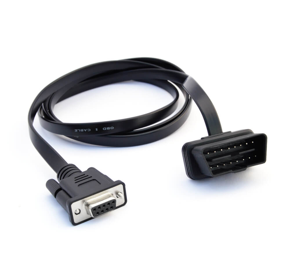
OBD2 adapter
In most cars (and some vans/trucks), this lets you request OBD2/UDS data. May also provide access to the car's proprietary CAN data
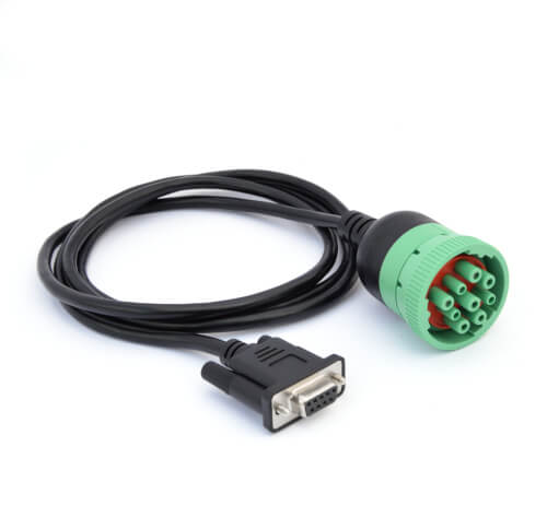
J1939 adapter
In most heavy-duty vehicles (trucks, buses, excavators, tractors, ...), this provides access to the raw CAN data (J1939 protocol)
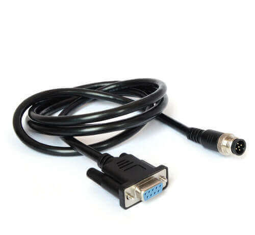
M12 adapter
In most maritime vessels (ships, boats) and some industrial machinery, this lets you record the raw CAN data (NMEA 2000 or CANopen)
Contactless
A universal option is to skip the connector entirely - and instead use induction to read data from the CAN high/low wiring harness directly
Depending on your use case, it may be simple or complex to determine the right adapter. Here we provide some additional tips based on the type of use case:
Cars
If your goal is to log data from your car, you will most likely need the OBD2 adapter. This lets you request OBD2 data from most non-EV cars after 2008 and usually get some responses such as RPM, speed, fuel level etc. If your car is an EV, you may be able to perform UDS requests using the OBD2 adapter. Similarly, if you are looking to reverse engineer proprietary CAN data, you can use the OBD2 adapter if your car provides access through the OBD2 connector to the proprietary CAN data. Note, however, that this is not always the case - in which case you would instead need to use a contactless CAN reader.


Heavy-duty
In heavy-duty vehicles, the J1939 adapter is the most commonly used. If you can identify a black/green 9-pin deutsch J1939 connector in your vehicle, then you can use this adapter. However, many vehicle brands use other connectors, like the Caterpillar 9-pin connector. Therefore, we generally recommend to get both a J1939 adapter and contactless CAN reader to provide multiple options for connecting to the J1939 data. In some heavy-duty veihcles a single J1939 9-pin connector may provide access to two CAN buses, in which case you can consider the J1939-DB9/DB9 adapter. In some trucks (e.g. from Volvo) you can access J1939 data via the OBD2 connector. Here our OBD2-DB9/DB9 adapter can be useful.
Maritime
In marine vessels, you will most often encounter the M12 connector that provides access to the NMEA 2000 data of the boat/ship. In some cases, you may be looking to collect data directly from the vessel engines, in which case you may use e.g. the J1939 adapter or DT06 adapter.


Industrial machinery
In non-automotive industrial machinery, you will often be able to use the M12 adapter. You may also encounter the standard DB9 connector, though you should then ensure that this reflects a connector for CAN access and not e.g. an RS232 interface.
Agriculture
In tractors, you can typically use the J1939 adapter to record J1939 data from the vehicle. However, you may also be interested in collecting ISOBUS data in parallel to the J1939 data. Here, a J1939-DB9/DB9 adapter (H+J) can be used as it provides access to both the tractor's J1939 network and the ISOBUS network related to the tractor implement. Alternatively, you may use the in-cab adapter to access the ISOBUS network.


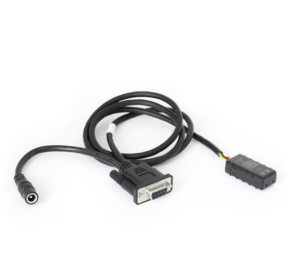
Labs & test benches
If you are working in a non-field environment, you may prefer instead to use a generic adapter that provides open-wire connections for quickly connecting to power and an active CAN bus. Similarly, an open wire adapter can be useful as a starting point for creating your own custom adapter cables if no off-the-shelf adapter matches your application.
Universal
Regardless of your application, you can in principle always use a contactless CAN reader. As long as you are able to get access to the physical CAN bus wiring harness (CAN high/low), then you can connect a contactless CAN reader to start recording CAN data. This is non-invasive and therefore often used in e.g. large-scale deployments to avoid issues with vehicle warranty. However, contactless CAN readers can be more cumbersome to install as you need to e.g. remove panels or similar to expose the wires - which may be less ideal for quick test deployments. Further, other adapter cables typically provide power/ground from within the same connector (through separate pins from the CAN bus) for easy plug & play installation. With a contactless CAN reader, you need to e.g. use a cigarette-to-DC adapter or similar to provide external power. Finally, contactless CAN readers are 'read-only' - no messages can be transmitted onto the CAN bus. This is often a 'feature' - but it also means that you cannot use such an adapter to e.g. perform requests over the CAN bus. Hence this solution does not allow you to e.g. perform OBD2/UDS requests.

Most modern vehicles do not simply have one CAN bus. There can be other automotive protocols in play like LIN bus, FlexRay and Automotive Ethernet. Further, many vehicles (in particular heavy-duty) will have multiple CAN buses. For example, most commercial trucks have 2 or 3 separate CAN buses, while some mining vehicles may have more than 8 separate CAN buses. This is important to keep in mind when you are trying to collect data: You may need to connect to multiple CAN buses in parallel to collect all the data you need - and the first CAN bus you identify does not necessarily contain the data you need.
Many CAN loggers enable you to log multiple CAN buses in parallel. This is important as you generally need to ensure a high degree of time synchronization in order to be able to perform meaningful analysis across the different networks. As an example, the CANedge by default lets you record 2 x CAN networks in perfect time synchronization. Further, by adding a CANmod.router, a single CANedge can effectively record 5 x CAN channels.
Similarly, the CANsub lets you stream 2 x CAN or 4 x CAN channels in parallel in real-time via USB or Ethernet, critical in understanding multi-CAN applications.
#3: Configure and connect your device
Before you connect your device, consider two things:
- Baud-rate: Your device baud-rate must match the CAN bus. If you connect to an active CAN bus, some devices (like the CANedge) can auto-detect the baud-rate to simplify this
- Requests: If you aim to record on-request data like OBD2/UDS, you must configure your device to transmit the relevant 'request messages'
You can now connect your device and verify that it logs data. If not, see our top 10 troubleshooting tips (illustration).


#4: Review your raw CAN data
Once you are done recording e.g. a vehicle trip, you can review the resulting log file. In the picture, we show a log file with raw CAN data (J1939) recorded using a CANedge in a heavy-duty truck. Specifically, the data is displayed in a tabular structure in a software tool called asammdf. Notice how every line reflects a timestamped CAN frame incl. a CAN ID and data payload.
Tip: Download asammdf and our sample data to try it yourself.
How to decode raw CAN data to 'physical values'
The log file picture above illustrates an important point:
Raw CAN bus data is not human-readable.
To interpret it, you need to decode the CAN frames into scaled engineering values aka physical values (km/h, degrees, ...). This requires a DBC file and software tool.
Below we explain how this works in 3 steps:


#1: Understand CAN signal extraction
Each CAN frame contains CAN signals in the data payload.
For example, a CAN message from our CANmod.temp contains 9 CAN signals, incl. CJTemp (Cold Junction Temperature).
To extract the physical value of a CAN signal, the following information is required:
- Byte order: Whether data is encoded Intel or Motorola
- Bit start: Which bit the signal starts at
- Bit length: The length of the signal in bits
- Offset: Value to offset the signal value by
- Scale: Value to multiply the signal value by
To extract a CAN signal, you 'carve out' the relevant bits, take the decimal value and perform a linear scaling as illustrated.
#2: Get the relevant DBC file
As shown, interpreting raw CAN data requires information about how CAN signals are encoded. This is where a DBC is key.
A CAN DBC file (CAN database) is a text file that contains information for decoding raw CAN data.
But how do you get a DBC file?
Generally, DBC files are application-specific and proprietary and available only to the Original Equipment Manufacturer (OEM).
If you work as an OEM engineer you will typically have the DBC already (or the information to create one).

 Examples of standardized DBC
files
Examples of standardized DBC
files
If you are not the OEM, consider instead below routes:
- Check the docs: Products intended for integration often include a DBC (e.g. sensors)
- Ask the OEM: An OEM may share full/partial DBC files with partners or customers
- Use a standard DBC: For some protocols, OEMs agree on how to encode common signals. As a result, a J1939 DBC lets you decode 60-80% of signals across most heavy-duty vehicles. Similarly for the ISOBUS DBC, NMEA 2000 DBC, OBD2 DBC
- Reverse engineer: For some cars/EVs you can find reverse engineered DBC files (see e.g. our car/EV collections) - and otherwise you can try it yourself
- Externalize: Use sensor-to-CAN modules to 'fill proprietary gaps', e.g. for GPS, temperature or analog data
#3: Use a software/API tool
Finally, you will need a software/API tool that supports your log file format and DBC files.
The relevant software depends on your use case - below are examples for the CANedge/CANsub:
asammdf GUI
GUI desktop tools are useful for ad hoc analysis, diagnostics and export
Grafana dashboards
Customized dashboards enable data visualization, reporting and insight sharing
webCAN
webCAN lets you stream raw/decoded CAN data in your browser in real-time
Logging CAN data - example use cases
There are several common use cases for recording CAN bus data:

Logging/streaming data from cars
OBD2 data from cars can e.g. be used to reduce fuel costs, improve driving, test prototype parts and insurance
obd2 logging
Heavy duty fleet telematics
J1939 data from trucks, buses, tractors etc. can be used in fleet management to reduce costs or improve safety
j1939 telematics
CAN bus predictive maintenance
Vehicles and machinery can be monitored via IoT CAN loggers in the cloud to predict and avoid breakdowns
predictive maintenance
Vehicle/machine blackbox
A CAN logger can serve as a 'blackbox' for vehicles or equipment, providing data for e.g. disputes or diagnostics
can bus blackboxDo you have a CAN logging/streaming use case? Reach out for free sparring!
Contact usFor more intros, see our guides section - or download the 'Ultimate Guide' PDF.
Need to log/stream CAN bus data?
Get your CAN logger/interface today!


