ISOBUS (ISO 11783) Explained - A Simple Intro [2026]

Need a simple, practical intro to ISOBUS (ISO 11783)?
In this guide we introduce the ISOBUS protocol used in agricultural vehicles (like tractors) and implements (like sprayers, seeders). In particular, we'll cover the ISO 11783 standards, history, the link to J1939 and connectors.
To ensure this stays practical, we also explain how to record and decode ISOBUS data - with practical use cases and dashboard playground examples.
Learn more below!
In this article

What is ISOBUS?
ISOBUS (ISO 11783) is a standardised communication protocol used in agriculture and forestry machinery. The main purpose is to enable plug & play integration between vehicles (e.g. tractors) and implements (e.g. sprayers) across manufacturers.
The protocol is based on the Controller Area Network (CAN bus). Specifically, it has been derived from the SAE J1939 protocol used in most heavy-duty vehicles (including most tractors).
Today, ISOBUS is implemented in most modern tractors and implements (like balers, sprayers, fertilizers, seed drills) and enables standardised communication between them.
For example, a tractor may use J1939 internally. The Tractor ECU (TECU) then serves as a gateway to the tractor's ISOBUS network. Similarly, a sprayer may use e.g. J1939/CANopen internally, while an ISOBUS gateway facilitates the communication with the tractor. Assuming ISOBUS is properly implemented in both tractor and implement, the integration is seamless.
With certified ISOBUS solutions, end users avoid cluttering cabins with implement-specific terminals - and instead control any implement from a single universal terminal.

ISOBUS history and AEF
- 1991: ISO set up the initial working group (SC19 aka Working Group 1)
- 2001: ISOBUS started getting introduced in tractors and implements
- 2003-2005: ISOBUS made increasingly interoperable, in part via 'plugfests'
- 2008: The Agricultural Industry Electronics Foundation (AEF) was established
- 2022: AEF demonstrates High-Speed ISOBUS (HSI) based on Ethernet

AEF and ISOBUS certification
When ISOBUS solutions initially started rolling out in the early nineties, most were early-stage solutions. From 2001, ISOBUS experienced an adoption 'breakthrough' with tens of thousands of new ISOBUS tractors/implements sold globally.
However, in practice, the standard was complex and interpreted differently by manufacturers - causing incompatibility issues in the field (and a general loss of confidence in the ISOBUS promise). In response, AEF was established in 2008.
AEF originally comprised seven agriculture equipment manufacturers (John Deere, CNH, Claas, AGCO, Kverneland Group, Grimme, Pottinger) and two associations (Association of Equipment Manufacturers, AEM, and German Engineering Federation, VDMA). Today, FederUnacoma serves as the 3rd core member association, while there are now 8 manufacturer core members including KUHN. In total, more than 200 companies/institutions are now members of AEF.

AEF has a set of core objectives:
- Define guidelines for implementations of ISOBUS
- Coordinate improvements to ISOBUS incl. certification tests
- Coordinate collaboration in the agriculture industry
- Organize certification support, training and consulting
Further, AEF has developed a number of tools and products:
- AEF Conformance Test: Used by AEF accredited test labs to certify ISOBUS components
- AEF Database: Used by dealers/users globally to assess compatibility and conformance of ISOBUS components
The conformance testing and related database are vital in ensuring a consistent, standardized implementation of ISOBUS - allowing end users to lookup components across brands and manufacturers to ensure compatibility prior to purchase. This ensures that the original promise of a 'plug & play' cross-brand experience with ISOBUS vehicles and implements can be realized in practice.
ISOBUS OSI model & standards
Next, we will briefly consider the 7 layer OSI model for ISOBUS including the link to the 14 parts of ISO 11783 standard.
Note how we also reference CAN bus (ISO 11898) for the physical layer and data link layers, to reflect the role CAN plays as the basis for ISOBUS.
While not shown in the illustration, SAE J1939 also plays a role as reference for some of the layers/standard parts - for example, J1939-71 provides the definition for most power train messages as described in ISO 11783-8.
Below we briefly recap the 14 parts of the ISO 11783 standard:

This serves as an overview of the entire ISO 11783 standard collection, providing the basis for a standardized serial communication network between forestry/agriculture tractors and implements. It describes the OSI model layers and references the other standards.
This standard specifies the physical layer of the network. Since ISOBUS is based on CAN, this standard is closely linked to ISO 11898-2 describing the CAN bus physical layer. In addition, ISO 11783-2 describes ISOBUS specific connectors like the ISOBUS Breakaway Connector (IBBC).
This standard describes the ISOBUS message formats. Specifically, it dictates the use of extended CAN IDs and the use of J1939-style Parameter Group Numbers (PGN). The standard also specifies a transport protocol for the communication of multi-frame ISOBUS messages, i.e. data that exceeds the 8 bytes of Classical CAN frames.
Here, the use of 'network interconnect units' are described for connecting two separate networks with differing architectures. This gateway ensures both electrical and message isolation of each network.
This defines the process for determining source addresses (SA) and resolving address conflicts. Source addresses can be preset or dynamically claimed by each controller during power up.
This standard describes the virtual terminal as an ECU that provides the tractor operator with an interface for controlling the tractor and/or implement(s). The control should be exerted through the use of the standardized ISO 11783 messages. The VT is a core feature of ISOBUS.
This standard describes standardized application messages for the ISOBUS implement. This also serves as the basis for most of the messages in our ISOBUS DBC file. To some extent, this can be compared to J1939-71, which serves as the basis for most of the J1939 PGN and SPN decoding information. In the case of ISOBUS, messages described include e.g. wheel/ground based speed and direction, key switch state, aux valves, lights and more.
This describes powertrain messages used in the tractor network implementation. Effectively, it references the SAE J1939-71 standard, stating that any overlapping messages should be implemented as per J1939-71.
When an implement is connected to a tractor, it is critical to ensure consistent cross-communication. Here, the tractor ECU should allow the implement to request information from ECUs on the tractor network in accordance with ISO 11783-7, as well as respond to implement commands. This also describes details on safe mode operation.
A 'farm management computer' may be available on the implement network. This enables the operator (typically a farmer) to define tasks/actions for the implement to perform. The 'task controller' receives these tasks via an interface from the computer. The tasks are scheduled by the controller, which ensures execution in the implement through control functions. The controller also receives status information from the implement ECUs, which is parsed back to the farm management computer. The standard defines the operation of the task controller, including the standardized messages used for the control functions.
This is closely linked to 11783-10, providing a data dictionary to define the data elements used in the task controller messages.
This specifies messages used for diagnostics to identify faults and issues on the network. It can be compared to J1939-73
This defines an ECU that provides data storage on the network (e.g. for multimedia), as well as a set of commands for use by read/write data to the file server.
This more recent standard (first issued in 2013) details how to perform sequence control within the ISO 11783 network. Here, an operator can record sequences of control functions for later on-demand replay.
ISOBUS Functionalities
AEF refers to a number of ISO 11783 based 'products' as ISOBUS Functionalities. Effectively, these can be sold to end users as a separate modules on the ISOBUS. In this section we briefly detail each of the AEF ISOBUS Functionalities:

#1 Virtual Terminal (VT) / Universal Terminal (UT)
This refers to the Virtual Terminal specified in ISO 11783-6. The VT is sometimes referred to as an Universal Terminal (UT) because of the capability it provides: To allow the end user to operate different implements (even across brands/manufacturers) via a single terminal. We'll refer to it as the VT throughout.
The VT is a core part of what makes ISOBUS visually attractive: Instead of a messy tractor cabin containing a multitude of implement-specific displays, everything can now be handled through a single display - across all ISOBUS compatible implements.
In practice, the VT is initialized through a sequence of CAN messages being sent between the VT and the implement. Here, the VT informs the implement of its specifications, allowing the implement to send its user interface to the VT for graphical visualization. Once initialized, the operator can perform various implement control tasks through the VT.

#2 Tractor ECU (TECU)
The Tractor ECU (TECU) serves as a gateway between the tractor CAN bus (typically J1939) and the ISOBUS. The TECU provides selective info to the implement like speed, RPM etc. from the tractor network via the ISOBUS.
In more recent versions of Tractor ECUs, the implement can take over full control of the tractor - incl. steering, speed, braking, transmission etc. This enables increasingly autonomous solutions where tractor and implement operate seamlessly as a single system.
Note also that the implement often has a similar ECU, sometimes referred to as the Implement ECU (I-ECU). This serves as a gateway between the implement's internal CAN bus and the ISOBUS.

#3 Task Controller (TC)
The Task Controller is a piece of software that records and provides information on operations and assists in planning. It takes inputs from the operator via an interface and serves to schedule tasks for the implement, executing them through control functions. In particular, it allows for automated and thus more fine-grained control over the implement - key in e.g. precision farming.
The Task Controller consists of three sub protocols:
- Basic (TC-BAS): This is used for tracking data totals (e.g. how much product has been applied), with info provided by the implement. This makes it easy to e.g. extract documentation of the work done via the operator interface
- Section (TC-SEC): This enables automated switching of sections in e.g. a sprayer based on for example GPS position, allowing for more precise use of implement functionality
- Geo (TC-GEO): This is used for GPS-based task automation, such as executing geo-based seeding control. For example, this is useful if certain areas in a field need customized handling

#4 Auxiliary Control (AUX)
This ISOBUS Functionality often reflects a joystick or similar control element, which enables more fine-grained control over implement functionality. Note that both a new/old version exists which are not cross-compatible (AUX-N/AUX-O).

#5 Tractor Implement Management (TIM)
As mentioned in the TECU section, there is increasingly a demand for bi-directional control between tractor and implement, meaning in particular that the implement should eventually be able to control the tractor in some use cases. This would improve productivity and reduce operator fatigue.

#6 Logging of device values (LOG)
This is focused on logging data from the tractor/implement, independently of the task being executed. To some extent, it can be compared to retrofitting a CAN data logger to record all messages being communicated on the CAN buses. However, in the case of LOG, the aim is to allow for the data to be exported in the ISO XML format (similar to what is supported for Task Controller data).

#7 ISOBUS Shortcut Button (ISB)
This enables deactivation of selective implement functions. This can be relevant in use cases where multiple implements are being controlled from a single tractor Virtual Terminal. Here, one implement might be in the foreground, while the user needs to quickly deactivate functionality in another implement.
ISOBUS vs SAE J1939
A common question is how ISO 11783 (ISOBUS) relates to the SAE J1939 protocol.
In short, ISOBUS was originally derived from J1939 and a core goal of ISO 11783 is to remain compatible with J1939 through close alignment with SAE. In a sense, one can say that ISOBUS is today harmonized with J1939. This is useful as many tractor networks will be based on SAE J1939, meaning that Tractor ECUs (TECU) often need to serve as gateways between ISOBUS and J1939.

Further, various J1939 standards serve as direct references for the ISOBUS standards. For example, J1939-71 defines powertrain messages and serves as a reference for ISO 11783-8. Both ISOBUS and J1939 also rely on CAN bus (CAN 2.0B) as the lower layer for communication and both leverage the concept of 18 bit PGNs to identify messages.
However, J1939 is mainly used in 'closed systems' and therefore ISOBUS has been extended beyond J1939 to serve the need for plug & play implements. It is therefore important to note that ISOBUS is not equal to J1939. We outline a number of key differences in the table. For details see below:
In particular, note that the ISOBUS application layer includes a number of additional components, such as the Virtual Terminal and Task Controller.
ISOBUS also enables alternative transport protocol methods like Fast Packets e.g. for GNSS data (also known from NMEA 2000) and Extended Transport Protocol (e.g. for sending data to the VT or File Server). ISOBUS also introduces a number of Data Dictionary Identifiers, which are similar to SPNs - though they are generally transmitted with 1 SPN per message, rather than multiple. Due to the need for implement interoperability, dynamic address claiming is mandatory in ISOBUS, whereas it's often skipped in J1939 (due to the closed system logic). Further, ISOBUS introduces a number of alternative physical connectors vs. J1939 as we'll detail shortly.
The ISOBUS connectors
ISO 11783-2 describes a number of physical connectors used in tractors and implements.

#1 Bus extension connector
This connector enables the extension of the ISOBUS signal lines from the implement within the tractor. This is e.g. used for adding additional devices such as Virtual Terminals. The connector will be located in the tractor cabin on the right side of the operator's seat.

#2 Implement Bus Breakaway Connector
The IBBC enables the connection of implements to the tractor. The connector is located at the rear of the tractor. In some cases an optional IBBC may also be installed on the front of the tractor for use with implements that are front mounted. The IBBC must have a cap for covering it against dust and the weather when no implement is connected.

#3 In-cab connector (LBS)
The tractor cabin may include an optional in-cab connector for establishing a connection to the ISO 11783 network. This is sometimes referred to as LBS.

#4 Diagnostic connector
The diagnostic connector is located in the tractor cabin in a location that is easily accessible. As we'll detail shortly, the diagnostic connector can be a good option for connecting external data logging devices for diagnostics - in particular if you need access to both the J1939 and ISOBUS networks in parallel.
J1939-to-DB9/DB9 adapter (H + J)ISOBUS PGN and SPN [+ DBC]
ISO 11783 uses the concept of Parameter Group Numbers (PGN) and Suspect Parameter Numbers (SPN) from the SAE J1939 protocol. This means that messages are identified based on 18-bit PGNs, which can be extracted from the full 29-bit CAN identifiers. In turn, signals or parameters are referred to as SPNs and will be 'packaged' in the data payload of each message.
We will not cover the PGN structure in detail as it is already covered in our SAE J1939 intro. However, we will provide a few practical comments on ISOBUS PGNs and SPNs.

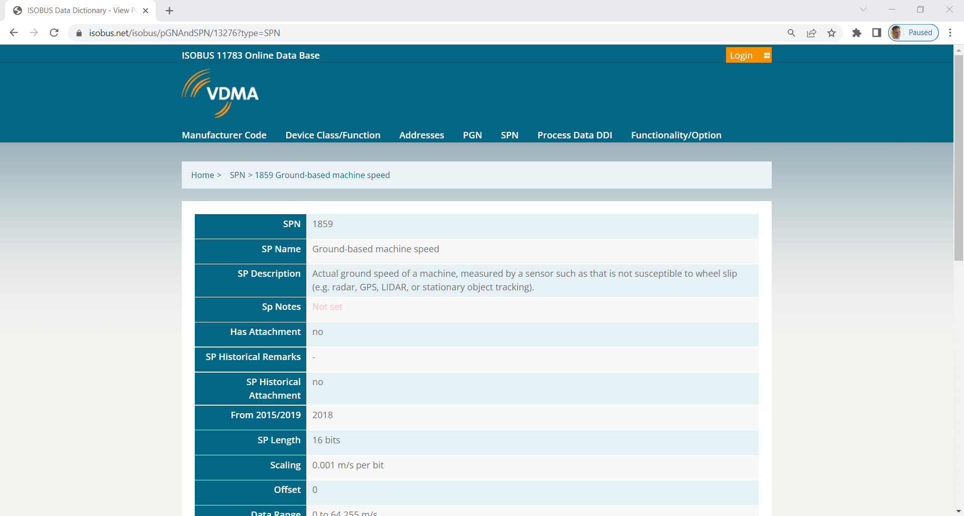
ISOBUS PGN and SPN database
The ISO 11783-7 standard specifies PGN and SPN details unique to ISOBUS. The decoding details are publicly available from the VDMA ISOBUS Data Dictionary. Signals include:
- Front/rear hitch pitch/roll/yaw angle
- Machine selected speed
- PTO information - rear shaft speed
- Engine speed, wheel based speed
- Tractor lights
The public database includes decoding rules for ~800 signals, of which ~650 can be directly transformed to a format useful in e.g. telematics and data logging. As explained below, we provide a DBC version of these ~650 ISO 11783 message decoding rules.
Note that the ISOBUS network may also contain OEM proprietary data that cannot be decoded using the public information.
ISOBUS vs. J1939 vs. NMEA 2000 [+ DBC files]
If you record data from a tractor/implement, multiple protocols (and hence DBC files) may be relevant.

ISOBUS data (implement/tractor)
Naturally, the ISOBUS network will contain data related to the communication between tractor and implement. This information will often be decodable using the ISO 11783-7 decoding rules mentioned above. To enable quick decoding of the standard ISOBUS data, you can use our ISOBUS DBC file.
Learn more
J1939 data (tractor)
If you record data directly from the tractor's CAN bus, it will most likely be J1939 data. Similarly, if you log data from the ISOBUS network, some of the data from the Tractor ECU will typically be J1939. In either case, the J1939 data requires the use of decoding rules from the J1939 Digital Annex. For this purpose, you can use our J1939 DBC file.
Learn more
NMEA 2000 data (GNSS)
Often, the ISOBUS network contains NMEA 2000 encoded GNSS information. The NMEA 2000 data may be broadcast as a combination of single-frames and NMEA 2000 Fast Packet TP frames. To decode the data, you can use our NMEA 2000 DBC file.
Learn more
OEM proprietary data (tractor/implement)
Of course, there will almost always be some messages that are proprietary regardless of the protocol. These are only known to the OEM (Original Equipment Manufacturer) and cannot be decoded using the standard DBC files. Sometimes these messages follow one of the above standards, though in other cases they may use another standard entirely (e.g. CANopen).
Example: Decoding data from an ISOBUS network
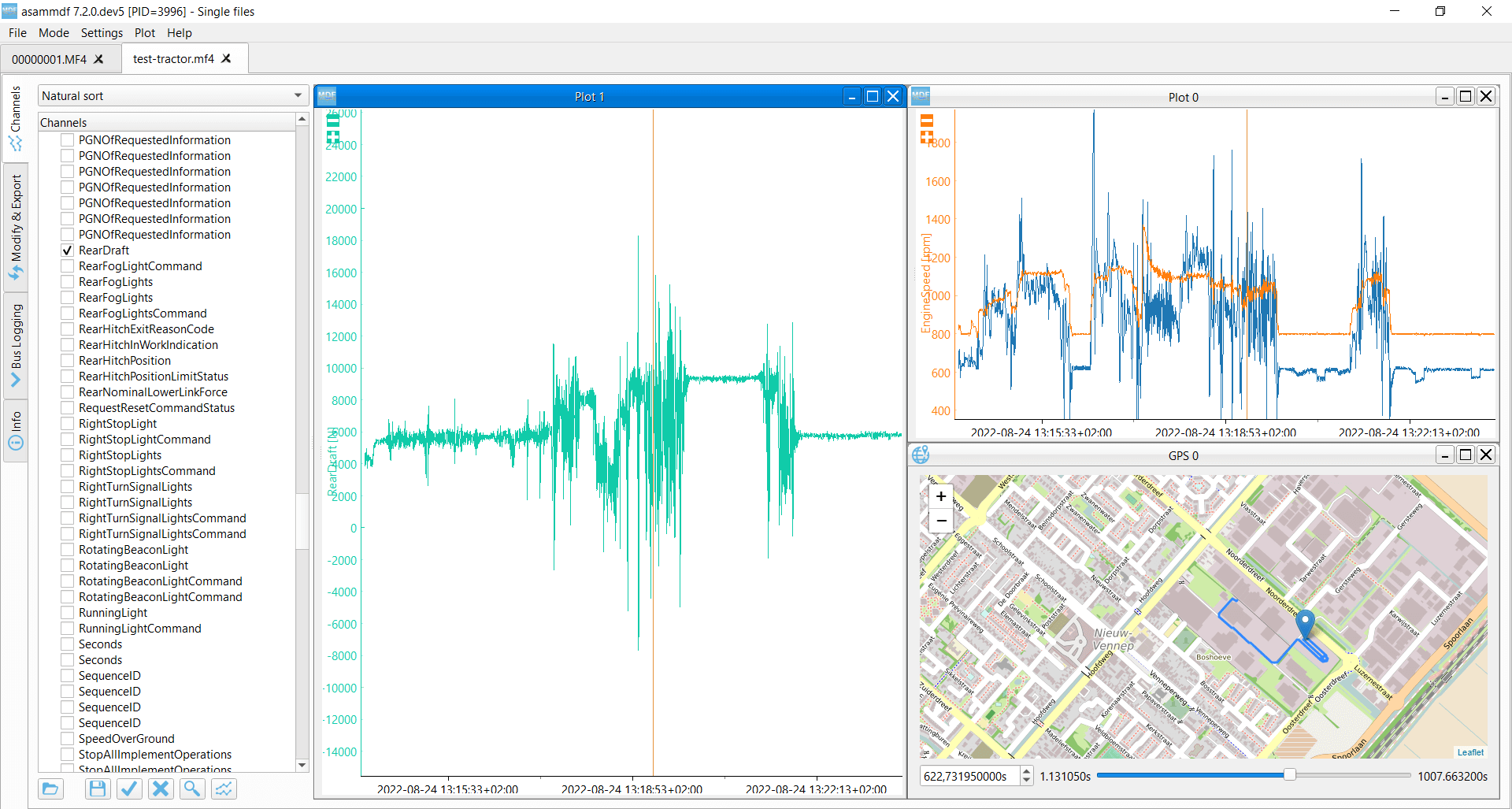
To exemplify the division that you'll often see in agriculture CAN bus data, consider a log file from a Fendt tractor with an implement from another manufacturer. In this case, a CANedge2 has been used to record data from the ISOBUS network. Through this, 337 unique CAN IDs have been recorded, corresponding to 38 unique PGNs.
The PGNs can be split by protocol as follows:
- ISOBUS DBC: 19 PGNs (~50%)
- NMEA 2000 DBC: 9 PGNs (~24%)
- J1939 DBC: 6 PGNs (~16%)
- Proprietary: 4 PGNs (~10%)
To get this ISOBUS sample data, get our J1939 data pack.
Note here that the connection of the CANedge2 was made on the ISOBUS network - not directly onto the J1939 network. As a result, there are very few decodable J1939 PGNs, since they only reflect the J1939 PGNs repeated by the Tractor ECU (TECU) onto the ISOBUS. Had the CANedge2 been connected to the J1939 network directly, there would be a significantly higher amount of CAN IDs overall - including many more J1939 PGNs.

Logging tractor/implement data
In this section we outline how you can record and process data from tractors/implements.
#1 How to choose a J1939/ISOBUS logger/interface
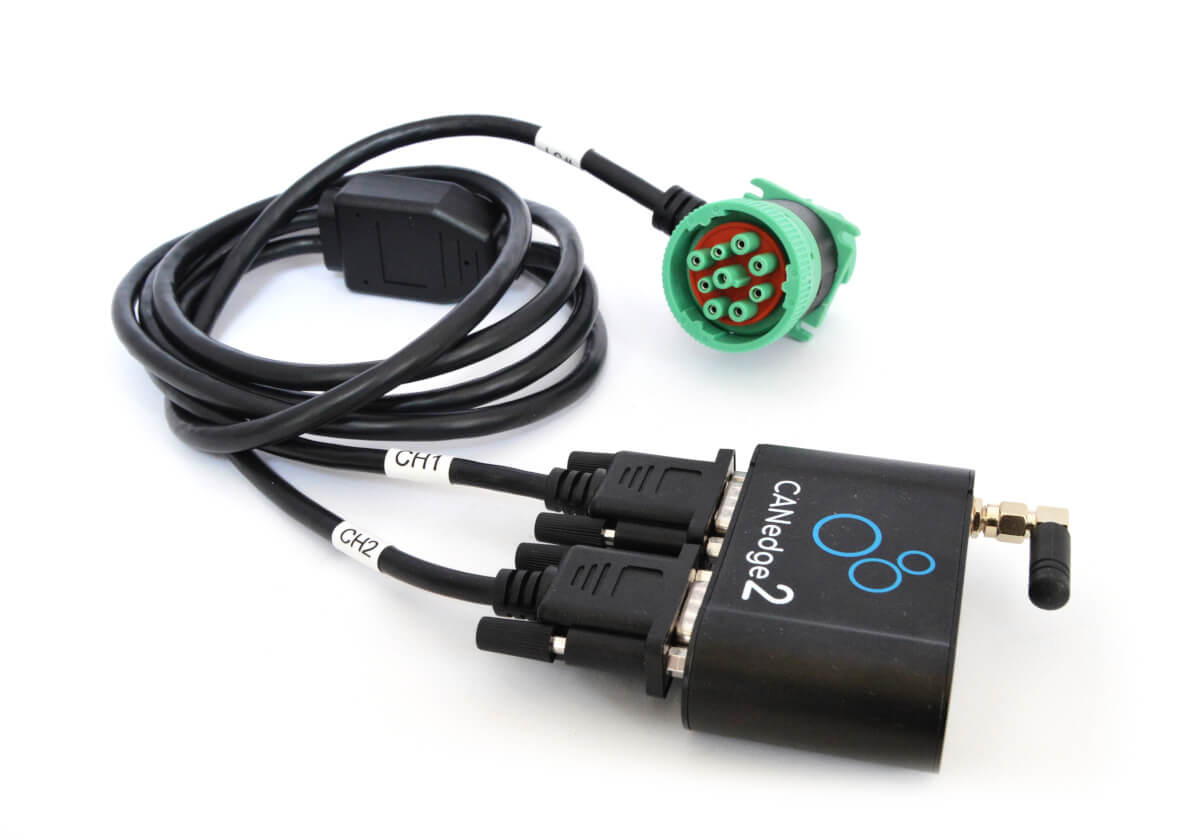
If you need to record your data offline, you can use the standalone CANedge1 to log 2 x CAN to an SD card. The device can be left in the tractor to record data for weeks or months. To collect the data, simply extract the SD card.
Alternatively, you can use the CANedge2 (WiFi) or CANedge3 (3G/4G) to automatically upload data to your own server (self hosted or cloud). This enables e.g. large-scale data collection, automated reporting or predictive maintenance.
If you deploy the CANedge in harsh environments it can be useful to protect it via our plug & play IP67 enclosure. The CANedge can be directly installed into the 100% dust-tight and waterproof enclosure - ensuring the robustoness and longevity of the device even in agricultural environments.
IP67 enclosure details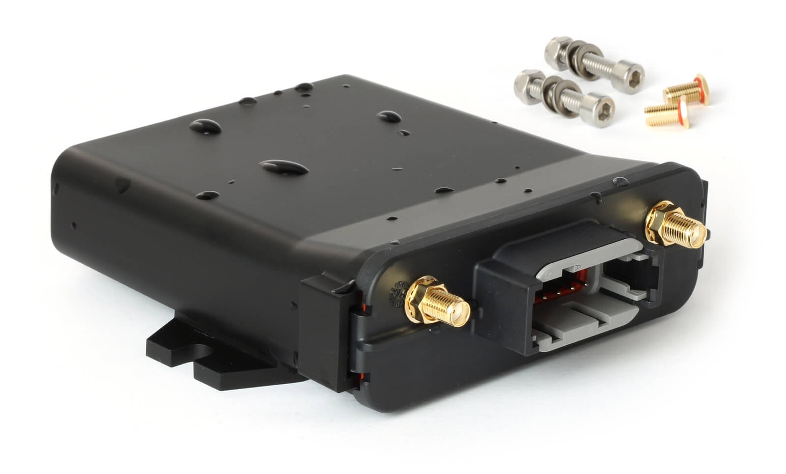
If you need to stream J1939/ISOBUS data in real-time, you can use the CANsub.2/CANsub.4 to stream 2-4 x CAN channels via USB or Ethernet directly into your browser via webCAN - with live J1939 PGN decoding, automatic J1939 TP (BAM/CM) reassembly and DBC decoding into named SPN signals.
#2 How to connect to the CAN bus
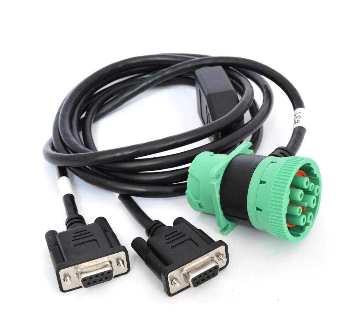
Once you've selected a CAN bus data logger, you'll need to identify how to interface with the CAN networks. We generally recommend to use the diagnostic connector if possible. As outlined previously, this enables access to both the J1939 network of the tractor - and the ISOBUS network.
You can use our J1939-DB9/DB9 (H + J) adapter cable, which perfectly matches the diagnostic connector pinout and enables you to log both the J1939 and ISOBUS networks separately into the same log file on the CANedge.
Alternatively, you can also use our regular J1939-DB9 adapter if you only need to access the J1939 network. Often many of the messages will be repeated across networks, so for many use cases this may suffice.
Note that if you aim to connect directly to an implement diagnostic connector (rather than through the tractor cabin), the CAN 1 pins (C + D) will typically give access to the implement's internal CAN bus - while H + J will still give access to the ISOBUS network.
#3 How to process the CAN data
To process the raw tractor/implement data, you'll need a suitable CAN software tool. Specifically, you'll load the log files and related DBC files to extract the physical values.
The CANedge software tools enable various forms of analysis. For example, you can use the MF4 converters to quickly convert the log files to popular file formats, for use in software like Vector CANalyzer or PEAK PCAN-Explorer. Or, you can use the asammdf GUI or our MF4 decoders to DBC decode the data and create visual plots.
You can also perform advanced data processing via the Python API - ideal if you need to perform statistical analysis, automated reporting or database integration. The Python API can also be used to integrate the data with dashboards - more below.
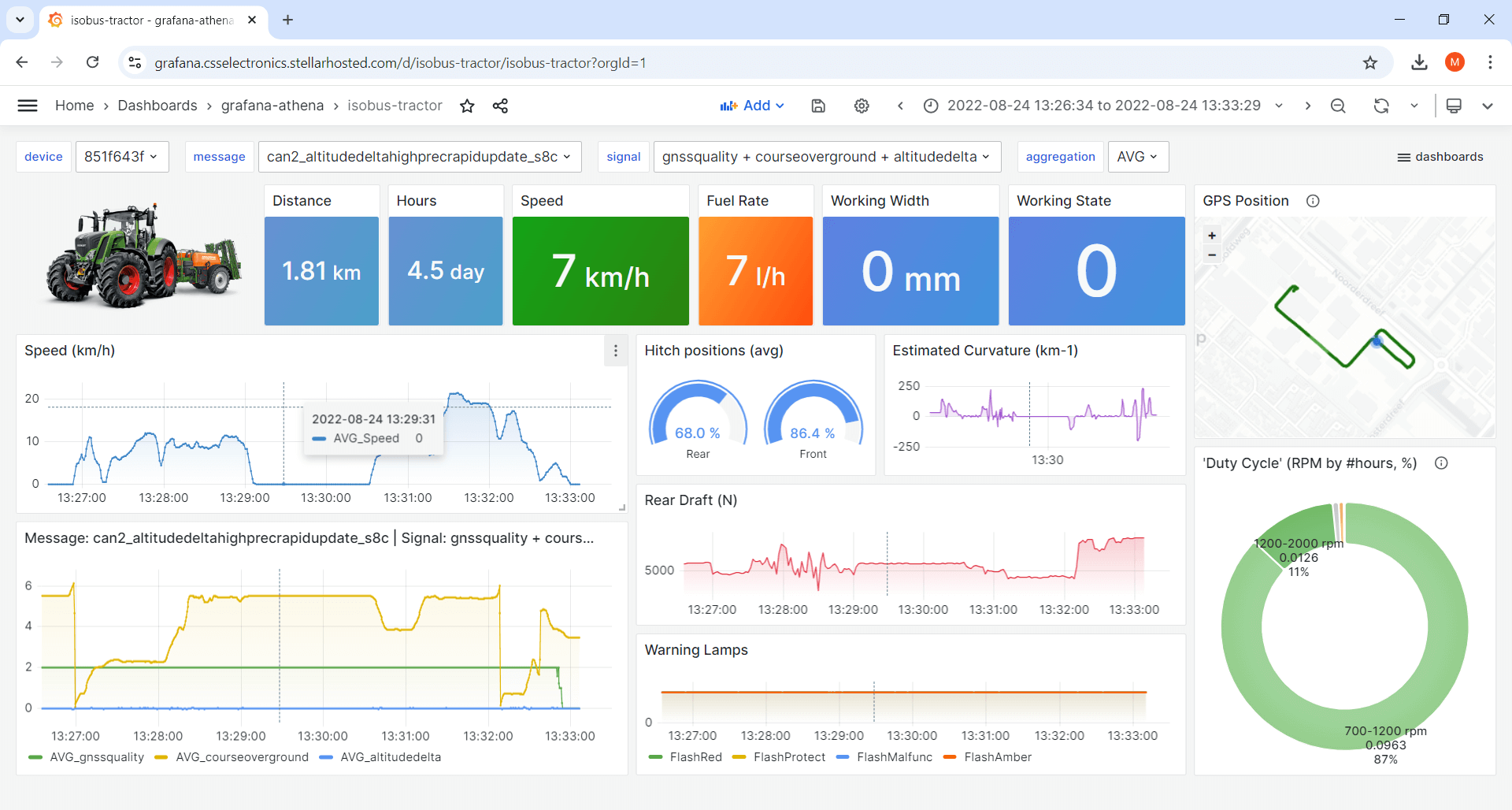
Example: Tractor dashboard with ISOBUS, J1939 and NMEA 2000 data
To illustrate the role of ISOBUS, J1939 and NMEA 2000 in tractor/implement data logging, check out our Grafana dashboard playground. Here, each signal is prefixed with the protocol from which it originates.
See also our telematics dashboard intro to learn more about Grafana dashboards.
The log file was recorded using a CANedge2 connected to the implement's diagnostic connector. Here, the CANedge2 specifically recorded data from the ISOBUS network. In other words, the log file does not include the tractor's internal J1939 data, except for the signals that are repeated onto the ISOBUS network.
To decode the data, we used both the J1939 DBC, ISOBUS DBC and NMEA 2000 DBC. We also leveraged the ISO TP functionality of the CANedge Python API to extract some of the NMEA 2000 Fast Packet data. Note that the proprietary OEM specific data is not included in the playground as this is not part of the standardized DBC files.
Data logging use case examples
Here we outline a number of classic data logging use cases within agriculture vehicles.

Tractor black box data logger
Need to capture intermittent issues - or handle warranty disputes?
By deploying a CAN bus data logger permanently in your tractors, you will gain access to a rolling window of insight into the full scope of your CAN bus networks. This makes it an ideal solution for capturing rare issues to speed up diagnostics - or to handle cases of warranty disputes between the OEM and end user.
Monitoring operational agriculture data remotely
Need to remotely collect operational data for post analysis?
As an operator or systems integrator, you may need to collect data across a fleet of agriculture vehicles in the field. Here, the CANedge3 can be deployed to log raw CAN data along with internal GPS/IMU data. The log files can be uploaded in the field at a configurable frequency. Using the CANedge Python API, it's easy to perform big data processing, advanced statistical analyses and reports - as in e.g. this case study.


Real-time J1939/ISOBUS streaming via CANsub
Need to stream J1939 and ISOBUS data from tractors and implements in real-time?
The CANsub.2/CANsub.4 can be connected to the J1939 or ISOBUS bus of a tractor or implement and routed to a WiFi router on the machine. Field technicians, service engineers and OEMs can then connect to the device wirelessly from their laptop or tablet in the cab - viewing live J1939 PGNs and ISOBUS messages directly in their browser via webCAN, with automatic J1939 TP and NMEA 2000 Fast Packet reassembly.

Case study: ISOBUS telematics
Learn how Kverneland uses the CANedge2 to collect ISOBUS and J1939 data from R&D implements - collecting the data via LTE to their own Azure cloud server for automated processing and dashboard visualization.
"The CANedge2 is a high quality product, but the support from CSS makes it an absolutely unbeatable solution!"
full case study 50+ case studiesFor more intros, see our guides section - or download the 'Ultimate Guide' PDF.
Need to collect ISOBUS data?
Get your CAN logger today!


