UDS Explained - A Simple Intro (Unified Diagnostic Services)
Need a simple intro to UDS (Unified Diagnostic Services)?
In this practical tutorial, we introduce the UDS protocol basics with focus on UDS on CAN bus (UDSonCAN) and Diagnostics over CAN (DoCAN). We also introduce the ISO-TP protocol and explain the difference between UDS, OBD2, WWH-OBD and OBDonUDS.
Finally, we'll explain how to request, record & decode UDS messages - with practical examples for logging EV State of Charge and the Vehicle Identification Number (VIN).
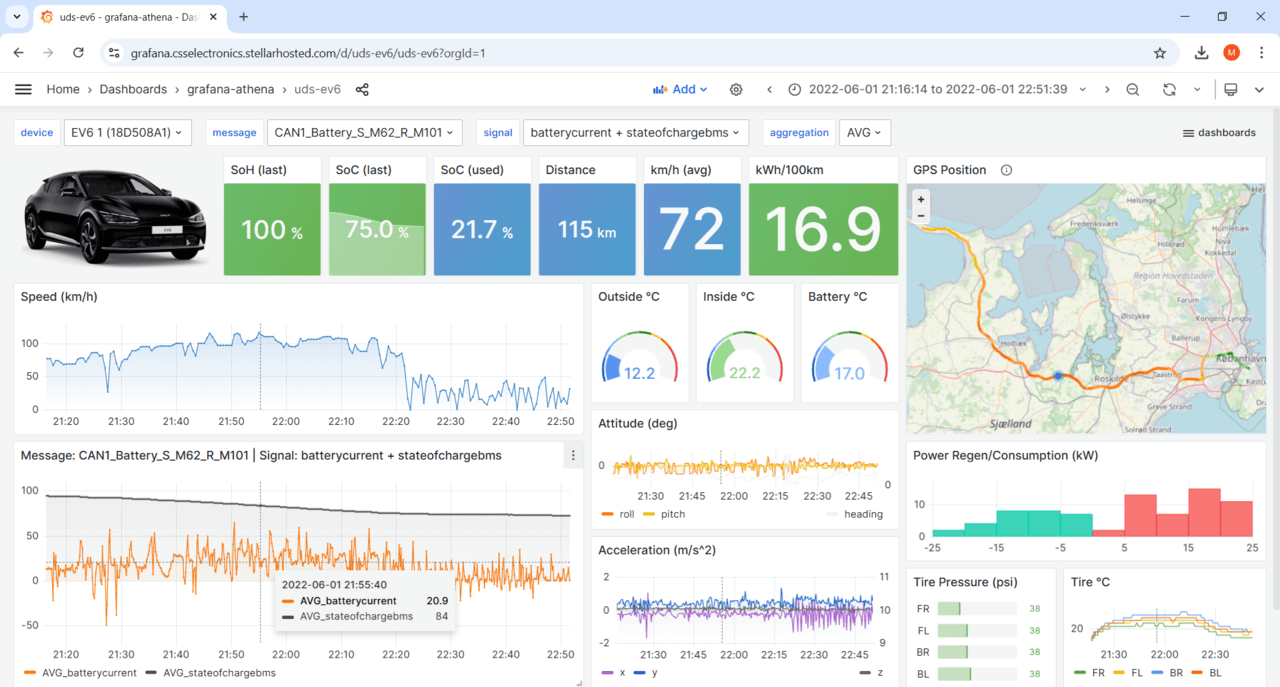
Bonus: We will also show how UDS data can be visualized in dashboards:
In this article
- What is UDS?
- UDS vs CAN (OSI model & standards)
- UDS message structure
- Positive/negative responses
- CAN ISO-TP (Transport Protocol)
- UDS, OBD2, WWH-OBD, OBDonUDS
- Request/record UDS data
- Ex1: Single Frame UDS data (Speed)
- Ex2: Multi frame UDS data (SoC%)
- Ex3: VIN via UDS, OBD2, WWH-OBD
- Ex4: DTCs via WWH-OBD
- UDS data logging - applications

What is the UDS protocol?
Unified Diagnostic Services (UDS) is a communication protocol used in automotive Electronic Control Units (ECUs) to enable diagnostics, firmware updates, routine testing and more.
The UDS protocol (ISO 14229) is standardized across both manufacturers and standards (such as CAN, KWP 2000, Ethernet, LIN). Further, UDS is today used in ECUs across all tier 1 Original Equipment Manufacturers (OEMs).
In practice, UDS communication is performed in a client-server relationship - with the client being a tester-tool and the server being a vehicle ECU. For example, you can connect a CAN bus interface to the OBD2 connector of a car and send UDS requests into the vehicle. Assuming the targeted ECU supports UDS services, it will respond accordingly.

In turn, this enables various use cases:
- Read/clear diagnostic trouble codes (DTC) for troubleshooting vehicle issues
- Extract parameter data values such as temperatures, state of charge, VIN etc
- Initiate diagnostic sessions to e.g. test safety-critical features
- Modify ECU behavior via resets, firmware flashing and settings modification
UDS is sometimes referred to as 'vehicle manufacturer enhanced diagnostics' or 'enhanced diagnostics' - more on this below.
UDS vs CAN bus: Standards & OSI model
To better understand UDS, we will look at how it relates to CAN bus and the OSI model.
As explained in our CAN bus tutorial, the Controller Area Network serves as a basis for communication. Specifically, CAN is described by a data-link layer and physical layer in the OSI model (as per ISO 11898). In contrast to CAN, UDS (ISO 14229) is a 'higher layer protocol' and utilizes both the session layer (5th) and application layer (7th) in the OSI model as shown below:

Overview of UDS standards & concepts
UDS refers to a large number of standards/concepts, meaning it can be a bit overwhelming. To give you an overview, we provide a high level explanation of the most relevant ones below (with focus on CAN as the basis). We detail some of these further below.
In the following we provide a quick breakdown of each layer of the OSI model:
- Application: This is described by ISO 14229-1 (across the various serial data link layers). Further, separate ISO standards describe the UDS application layer for the various lower layer protocols - e.g. ISO 14229-3 for CAN bus (aka UDSonCAN)
- Presentation: This is vehicle manufacturer specific
- Session: This is described in ISO 14229-2
- Transport + Network: For CAN, ISO 15765-2 is used (aka ISO-TP)
- Data Link: In the case of CAN, this is described by ISO 11898-1
- Physical: In the case of CAN, this is described by ISO 11898-2
As illustrated, multiple standards other than CAN may be used as the basis for UDS communication - including FlexRay, Ethernet, LIN bus and K-line. In this tutorial we focus on CAN, which is also the most common lower layer protocol.
The ISO 14229-1 standard describes the application layer requirements for UDS (independent of what lower layer protocol is used). In particular, it outlines the following:
- Client-server communication flows (requests, responses, ...)
- UDS services (as per the overview described previously)
- Positive responses and negative response codes (NRCs)
- Various definitions (e.g. DTCs, parameter data identifiers aka DIDs, ...)
The purpose of 14229-3 is to enable the implementation of Unified Diagnostic Services (UDS) on Controller Area Networks (CAN) - also known as UDSonCAN. This standard describes the application layer requirements for UDSonCAN.
This standard does not describe any implementation requirements for the in-vehicle CAN bus architecture. Instead, it focuses on some additional requirements/restrictions for UDS that are specific to UDSonCAN.
Specifically, 14229-3 outlines which UDS services have CAN specific requirements. The affected UDS services are ResponseOnEvent and ReadDataByPeriodicIdentifier, for which the CAN specific requirements are detailed in 14229-3. All other UDS services are implemented as per ISO 14229-1 and ISO 14229-2.
ISO 14229-3 also describes a set of mappings between ISO 14229-2 and ISO 15765-2 (ISO-TP) and describes requirements related to 11-bit and 29-bit CAN IDs when these are used for UDS and legislated OBD as per ISO 15765-4.
This describes the session layer in the UDS OSI model. Specifically, it outlines service request/confirmation/indication primitives. These provide an interface for the implementation of UDS (ISO 14229-1) with any of the communication protocols (e.g. CAN).
For UDS on CAN, ISO 15765-2 describes how to communicate diagnostic requests and responses. In particular, the standard describes how to structure CAN frames to enable communication of multi-frame payloads. As this is a vital part of understanding UDS on CAN, we go into more depth in the next section.
When UDS is based on CAN bus, the physical and data link layers are described in ISO 11898-1 and ISO 11898-2. When UDS is based on CAN, it can be compared to a higher layer protocol like J1939, OBD2, CANopen, NMEA 2000 etc. However, in contrast to these protocols, UDS could alternatively be based on other communication protocols like FlexRay, Ethernet, LIN etc.
When talking about UDS based on CAN bus, you'll often see two terms used: UDSonCAN (UDS on CAN bus) and DoCAN (Diagnostics on CAN bus). Some UDS tutorials use these terms interchangeably, which may cause confusion.
In ISO 14229-1 the terms are used as in our OSI model illustration. In other words, UDSonCAN is used to refer to ISO 14229-3, while DoCAN is used to refer to ISO 15765-2 aka ISO-TP.
However, part of the confusion may arise because ISO 14229-3 also provides an OSI model where DoCAN is both used in relation to ISO 15765-2 and as an overlay across OSI model layers 2 to 7. In ISO 14229-2, DoCAN is referred to as the communication protocol on which UDS (ISO 14229-1) is implemented. This is in sync with the illustration from ISO 14229-3. In this context, DoCAN can be viewed as a more over-arching term for the implementation of UDS on CAN, whereas UDSonCAN seems consistently to refer to ISO 14229-3 only.
UDS on CAN bus (UDSonCAN) is sometimes referred to through ISO 15765-3. However, this standard is now obsolete and has been replaced by ISO 14229-3.

UDS - no standard connector?
Unlike other higher-layer CAN protocols like OBD2, J1939 and ISOBUS, UDS does not specify a standard connector to be used for connecting external diagnostic equipment.
However, in practice the OBD2 connector (SAE J1962) is used in most vehicles. For example, electric vehicles from Nissan, Hyundai and VW support limited or no OBD2 communication, but do respond to UDS requests via the OBD2 connector.
UDS message structure [ISO 14229-1/3]
UDS is a request based protocol. In the illustration we've outlined an example of an UDS request frame (using CAN bus as basis):

A diagnostic UDS request on CAN contains various fields that we detail below:
#1 Protocol Control Information (PCI)
The PCI field is not per se related to the UDS request itself, but is required for diagnostic UDS requests made on CAN bus and is related to ISO-TP (ISO 15765-2), as will be detailed below. The example illustration is a 'Single Frame' ISO-TP CAN message.
#2 UDS Service ID (SID)
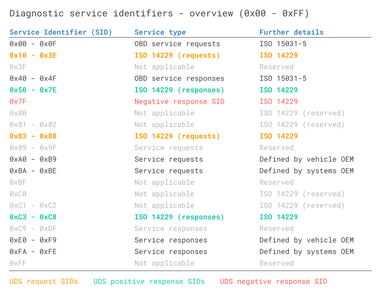
The use cases outlined above relate to different UDS services. When you wish to utilize a specific UDS service, the UDS request message should contain the UDS Service Identifier (SID) in the data payload. Note that the identifiers are split between request SIDs (e.g. 0x22) and response SIDs (e.g. 0x62). As in OBD2, the response SIDs generally add 0x40 to the request SIDs.
See also the overview of all standardized UDS services and SIDs. We will mainly focus on UDS service 0x22 in this article, which is used to read data (e.g. speed, SoC, temperature, VIN) from an ECU.
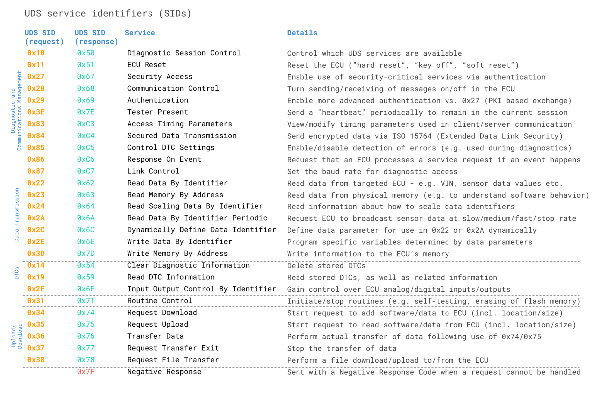
The standardized UDS services shown above are in practice a subset of a larger set of diagnostic services - see below overview. Note here that the SIDs 0x00 to 0x0F are reserved for legislated OBD services (more on this later).
As evident, UDS enables extensive control over the vehicle ECUs. For security reasons, critical UDS services are therefore restricted through an authentication process. Basically, an ECU will send a 'seed' to a tester, who in turn must produce a 'key' to gain access to security-critical services. To retain this access, the tester needs to send a 'tester present' message periodically.
In practice, this authentication process enables vehicle manufactures to restrict UDS access for aftermarket users and ensure that only designated tools will be able to utilize the security-critical UDS services.
Note that the switching between authentication levels is done through diagnostic session control, which is one of the UDS services available. Vehicle manufactures can decide which sessions are supported, though they must always support the 'default session' (i.e. which does not involve any authentication). With that said, they decide what services are supported within the default session as well. If a tester tool switches to a non-default session, it must send a 'tester present' message periodically to avoid being returned to the default session.
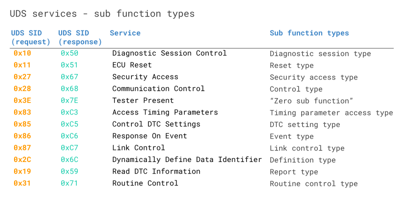
#3 UDS Sub Function Byte
The sub function byte is used in some UDS request frames as outlined below. Note, however, that in some UDS services, like 0x22, the sub function byte is not used.
Generally, when a request is sent to an ECU, the ECU may respond positively or negatively. In case the response is positive, the tester may want to suppress the response (as it may be irrelevant). This is done by setting the 1st bit to 1 in the sub function byte. Negative responses cannot be suppressed.
The remaining 7 bits can be used to define up to 128 sub function values.
Example: Service 0x19 sub functions
When reading DTC information via SID 0x19 (Read Diagnostic Information), the sub function can be used to control the report type (as per the table).
For example, sub function byte 0x02 lets you read DTCs via a status mask. In this case, the sub function byte is followed by a 1-byte parameter called DTC Status Mask to provide further information regarding the request (more on this below). Another common example is sub function byte 0x42, used in reading DTCs via WWH-OBD. In this case, 3 additional bytes are provided to configure the request (see also our trace example later in this article).

#4 UDS 'Request Data Parameters' - incl. Data Identifier (DID)
In most UDS request services, various types of request data parameters are used to provide further configuration of a request beyond the SID and optional sub function byte.
Example: Service 0x22 DIDs
An important example is service 0x22 (Read Data by Identifier). This service uses a Data Identifier (DID), which is a 2-byte value between 0 and 65535 (0xFFFF). The DID serves as a parameter identifier for both requests/responses (similar to how the parameter identifier, or PID, is used in OBD2). Notice that service 0x22 does not use a sub function byte.
For example, a request for reading data via a single DID in UDS over CAN would include the PCI field, the UDS service 0x22 and the 2-byte DID. Alternatively, one can request data for additional DIDs by adding them after the initial DID in the request.
We will look further into this in the section on how to record and decode UDS communication.
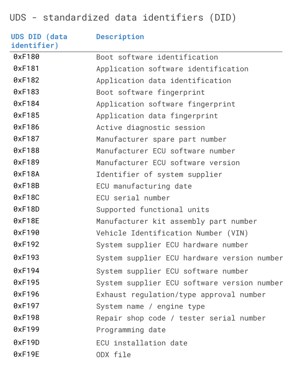
Data Identifiers can be proprietary and only known by OEMs, though some DIDs are standardized. This is for example the case for the WWH-OBD DIDs (more on this later) and the Vehicle Identification Number (VIN) is 0xF190. See the separate table for a list of standardized DIDs across UDS.
Positive vs. negative UDS responses [ISO 14229-1]
When an ECU responds positively to an UDS request, the response frame is structured with similar elements as the request frame. For example, a 'positive' response to a service 0x22 request will contain the response SID 0x62 (0x22 + 0x40) and the 2-byte DID, followed by the actual data payload for the requested DID. Generally, the structure of a positive UDS response message depends on the service.
However, in some cases an ECU may provide a negative response to an UDS request - for example if the service is not supported. A negative response is structured as in below CAN frame example:

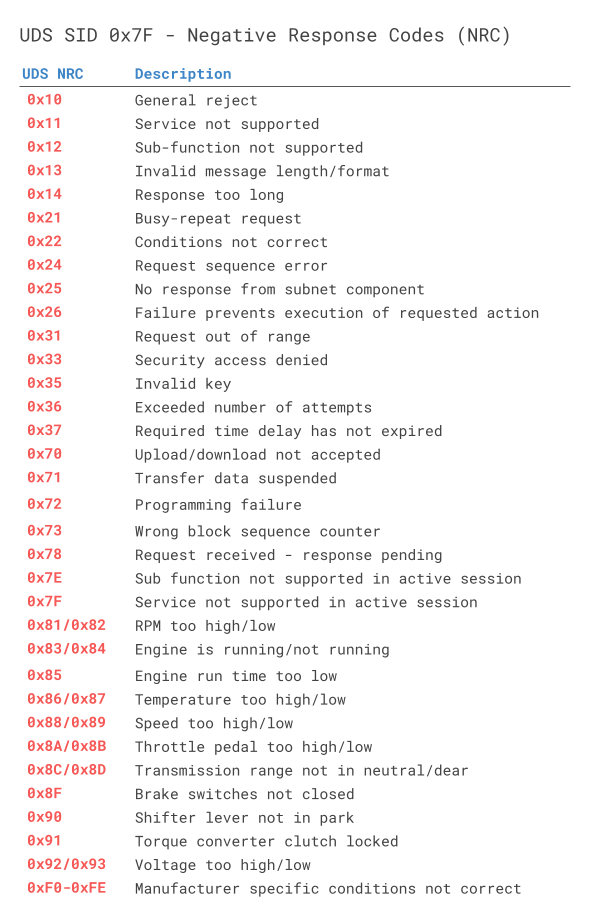
The negative response frame can be broken down as follows:
- The 1st byte is the PCI field (ISO-TP Single Frame)
- The 2nd byte is the Negative Response Code SID, 0x7F
- The 3rd byte is the SID of the rejected request
- The 4th byte is the Negative Response Code (NRC)
In the negative UDS response, the NRC provides information regarding the cause of the rejection as per the table. In this example, the frame implies that a request was made using SID 0x22 (to read data by identifier), but that it failed due to an invalid message format or length.
CAN ISO-TP - Transport Protocol [ISO 15765-2]
When implementing diagnostics on CAN, one challenge is the size of the CAN frame payload: For Classical CAN frames, this is limited to 8 bytes and for CAN FD the payload is limited to 64 bytes. Vehicle diagnostics often involves communication of far larger payloads.
ISO 15765-2 was established to solve the challenge of large payloads for CAN based vehicle diagnostics.
The standard specifies a transport protocol and network layer services for use in CAN based vehicle networks. The most common use cases include UDS (ISO 14229-1), OBD (SAE J1979, ISO 15031-5) and world-wide harmonized OBD aka WWH-OBD (ISO 27145).
The ISO-TP standard outlines how to communicate CAN data payloads up to 4095 bytes through segmentation, flow control and reassembly. ISO-TP defines specific CAN frames for enabling this communication as shown below:

The flow control frame is used to 'configure' the subsequent communication. It can be constructed as below:

A few comments:
- In the simplest case, the FC payload can be set to 30 00 00 00 00 00 00 00 (all remaining frames to be sent without delay)
- Alternatively, one can decide to perform more granular control over the communication by e.g. alternating between the Wait and Continue commands, as well as specifying a specific separation time (in milliseconds) between frames
- The ISO-TP frame type can be identified from the first nibble of the first byte (0x0, 0x1, 0x2, 0x3)
- The total frame size can be up to 4095 bytes (0xFFF) as evident from the FF frame
- The CF index runs from 1 to 15 (0xF) and is then reset if more data is to be sent
- Padding (e.g. 0x00, 0xAA, ...) is used to ensure the frame payloads equal 8 bytes in length
Below we outline how the ISO-TP protocol works for single-frame and multi-frame communication:
ISO-TP: Single-frame communication
In vehicle diagnostics, communication is initiated by a tester tool sending a request. This request frame is a Single Frame (SF).
In the simplest case, a tester tool sends a Single Frame to request data from an ECU. If the response can be contained in a 7-byte payload, the ECU provides a Single Frame response.


ISO-TP: Multi-frame communication
When the payload exceeds 7 bytes, it needs to be split across multiple CAN frames.
As before, a tester sends a Single Frame (SF) request to an ECU (sender). However, in this case the response exceeds 7 bytes.
Because of this, the ECU sends a First Frame (FF) that contains information on the total packet length (8 to 4095 bytes) as well as the initial chunk of data.
When the tester receives the FF, it will send a Flow Control (FC) frame, which tells the ECU how the rest of the data transfer should be transmitted.
Following this, the ECU will send Consecutive Frames (CF) that contain the remaining data payload.
ISO-TP plays an important role in most CAN based diagnostics protocols. Before we show practical examples of such communication flows, it is useful to get an overview of the most common vehicle diagnostic protocols.
UDS vs. OBD2 vs. WWH-OBD vs. OBDonUDS
A common question is how UDS relates to On-Board Diagnostics (OBD2), World-Wide Harmonized OBD (WWH-OBD) and OBDonUDS. To understand this, it is important to first note the following:
OBD (On-Board Diagnostics) is today implemented in different ways across countries and vehicles.
This is illustrated via the below OSI model comprising CAN based vehicle diagnostic protocols in use today:

Let's look at each diagnostic protocol:
- ISO OBD (or EOBD) refers to the OBD protocol specification legislated for use in EU cars, while SAE OBD refers to the OBD protocol specification legislated for use in US. The two are technically equivalent and hence often referred to simply as OBD or OBD2
- HD OBD (SAE J1939) typically refers to heavy duty OBD and is commonly implemented through the J1939 protocol in both US and EU produced vehicles with J1939-73 specifying diagnostic messages
- UDS (ISO 14229) has been implemented by vehicle manufacturers to serve the need for richer diagnostics data/functionality - beyond the limits of the emissions-focused OBD protocols. It is implemented in most ECUs today, across markets and vehicle types - though in itself, UDS does not offer the necessary standardization required to serve as an alternative to OBD
- WWH-OBD (and/or possibly OBDonUDS) provide an updated version of OBD2 for emissions-related diagnostics - based on UDS
To understand UDS, it is useful to better understand WWH-OBD and OBDonUDS:
What is WWH-OBD (ISO 27145)?
WWH-OBD is a global standard for vehicle diagnostics, developed by the UN under the Global Technical Regulations (GTR) mandate. It aims to provide a single, future-proof alternative to the existing OBD protocols (ISO OBD, SAE OBD, HD OBD). Further, WWH-OBD is based on UDS in order to suit the enhanced diagnostics functionality already deployed by most automotive OEMs today.
Moving from OBD2 to WWH-OBD will involve a number of benefits, primarily derived from using the UDS protocol as the basis.
First of all, the data richness can be increased. OBD2 parameter identifiers (PID) are limited to 1 byte, restricting the number of unique data types to 255, while the UDS data identifier (DID) is 2 bytes, enabling 65535 parameters.
For diagnostic trouble codes (DTCs), OBD2 would allow for 2-byte DTCs. Here, WWH-OBD allows for 'extended DTCs' of 3 bytes. This allows for grouping DTCs by 2-byte types and using the 3rd byte as a failure mode indicator to specify the DTC sub type.
Further, WWH-OBD enables a classification of DTCs based on how severe an issue is in regards to the exhaust emissions quality.
WWH-OBD also seeks to take potential future requirements into account by allowing for the Internet Protocol (IP) to be used as an alternative to CAN, meaning that UDSonIP will also be possible in future implementations of WWH-OBD. One potential benefit from this will be the ability to one day perform remote diagnostics through the same protocol.
The intent of WWH-OBD is to serve as a global standard, across all markets and across all vehicle types (cars, trucks, buses, ...). Further, the aim is to potentially expand the standardized functionality beyond just emissions-control.
In practice, WWH-OBD has been required in EU since 2014 for newly developed heavy duty vehicles (as per the Euro-VI standards). Note in this case that HD OBD (as per J1939) remains allowed in these vehicles.
Beyond this, however, the roll-out of WWH-OBD has been limited. One challenge is that WWH-OBD is currently not accepted by EPA/CARB in USA. However, recently OBDonUDS (SAE J1979-2) is being adopted in US.


What is OBDonUDS (SAE J1979-2)?
Similar to how OBD2 has been split into 'SAE OBD' (SAE J1979) for US and 'ISO OBD' (ISO 15031) for EU, the 'next generation' of OBD2 may again be regionally split.
Specifically, WWH-OBD (ISO 27145) has been adopted in EU for heavy duty vehicles already - but not yet in the US. Instead, it has recently been decided to adopt OBD on UDS in US vehicles in the form of the SAE J1979-2 standard, which serves as an update to the SAE J1979. The new SAE J1979-2 standard is also referred to as OBDonUDS. The aim is to initiate a transition phase starting in 2023, where ECUs are allowed to support either OBD2 or OBDonUDS. From 2027, OBDonUDS will be a mandatory requirement for all vehicles produced in the US.
To recap, WWH-OBD and OBDonUDS both serve as possible solutions for creating a 'next generation' protocol for emissions-related on-board diagnostics. It remains to be seen if the two will exist in parallel (like ISO/SAE OBD), or if one of the protocols will become the de facto standard across both US, EU and beyond.
In either case, the basis for emissions-related diagnostics will be UDS, which will serve to simplify ECU programming as the emissions-related diagnostics can increasingly be implemented within the same UDS based structure as the manufacturer specific enhanced diagnostics.
The CAN Calibration Protocol (CCP) and the Universal Measurement and Calibration Protocol (XCP) on CAN are CAN based higher layer protocols. These are typically used by automotive OEM engineers in early-stage prototype development, enabling measurement and calibration of ECUs. For further comparison vs. UDS, see our intro to CCP/XCP on CAN.
How to request/record UDS data
We have now gone through the basics of UDS and ISO-TP.
With this in place, we can provide some concrete guidance on how you can work with UDS data in practice. In particular, we will focus on how UDS can be used to log various data parameters - like state of charge (SoC) in electric vehicles.
Before the examples, we cover frequently asked questions on UDS data logging below:

Yes, as we'll show further below, the CANedge can be configured to request UDS data. Effectively, the device can be configured to transmit up to 64 custom CAN frames as periodic or single shot frames. You can control the CAN ID, CAN data payload, period time and delay.
For single-frame UDS communication, you simply configure the CANedge with the request frame, which will trigger a single response frame from the ECU.
For multi-frame communication, you can again configure the CANedge with a request frame and then add the Flow Control frame as a separate frame to be transmitted X milliseconds after the request frame. By adjusting the timing, you can set this up so that the Flow Control is sent after the ECU has sent the First Frame response.
The same applies for the CANsub.2/CANsub.4, which lets you stream raw CAN data and construct UDS request/flow control transmit sequences live via webCAN in your browser - with the added benefit of webCAN's built-in 'DBC encoder' for constructing transmit frames directly from a DBC file.

Note that the CANedge will record the UDS responses as raw CAN frames. You can then process and decode this data via your preferred software (e.g. Vector tools, Python or the MF4 decoders). The CANsub streams UDS responses live - and webCAN can DBC decode them on the fly into named signals (with ISO TP reassembly) for real-time analysis.
A common use case for recording or streaming UDS data via the CANedge or CANsub will be to acquire diagnostic trouble code values, e.g. for use in diagnosing issues.
In addition to the trouble codes, UDS lets you request the 'current value' of various sensors related to each ECU. This allows e.g. OEM engineers, vehicle fleet managers, researchers etc. to collect data of interest such as speed, RPM, state of charge, temperatures etc. from the vehicle (assuming they know how to request/decode the data).
Beyond the above, UDS can of course also be used for more low-level control of ECUs, e.g. resets and flashing of firmware. Such use cases are typically performed using a CAN bus interface like the CANsub.2/CANsub.4 rather than a standalone data logger - as bidirectional, real-time interaction with the ECU is required.
Importantly, UDS is a manufacturer specific diagnostic protocol.
In other words, while UDS provides a standardized structure for diagnostic communication, the actual 'content" of the communication remains proprietary and is in most cases only known to the manufacturer of a specific vehicle/ECU.
For example, UDS standardizes how to request parameter data from an ECU via the 'Read Data By Identifier" service (0x22). But it does not specify a list of standardized identifiers and interpretation rules.
With that said, vehicles that support WWH-OBD or OBDonUDS may support some of the usual OBD2 PIDs like speed, RPM etc via the usual PID values - but with a prefix of 0xF4 as shown in Example 1 below.
Generally, only the manufacturer (OEM) will know how to request proprietary parameters via UDS - and how to interpret the result. Of course, one exception to this rule is cases where companies or individuals successfully reverse engineer the information. Engaging in such reverse engineering is a very difficult task, but you can sometimes find public information and DBC files where others have done this exercise. Our intro to DBC files contain a list of public DBC/decoding databases.
Because of the proprietary nature of UDS communication, it is typically most relevant to automotive engineers working at OEMs. Tools like the CANedge CAN bus data logger allow these users to record raw CAN traffic from a vehicle - while at the same time requesting diagnostic trouble codes and specific parameter values via UDS.
Further, some after market users like vehicle fleet managers and even private persons can benefit from UDS assuming they are able to identify the reverse engineered information required to request and decode the UDS parameters of interest.
Logging UDS data will also become increasingly relevant assuming WWH-OBD gets rolled out as expected. Already today, WWH-OBD is used in EU heavy duty vehicles produced after 2014, meaning UDS communication will be relevant for use cases related to on-board diagnostics in these vehicles.
If you're looking to request UDS-based diagnostic trouble codes (DTC), you'll of course have to use UDS communication for this purpose. However, if your aim is to record current sensor values it is less clear.
Typically, data parameters of interest for e.g. vehicle telematics (speed, state of charge etc) will already be communicated between ECUs on the CAN bus in the form of raw CAN frames - without the need for a diagnostic tool requesting this information. That is because ECUs rely on communicating this information as part of their operation (as explained in our intro to CAN bus).
If you have direct access to the CAN bus, it would thus appear easier to simply log this raw CAN traffic and process it. If you are the vehicle manufacturer, you will know how to interpret this raw CAN data either way - and it'll be simpler to perform your device configuration and post processing in most cases. If you're in the aftermarket, it'll also be simpler to reverse engineer the raw CAN frames as you can focus on Single Frames - and avoid the request/response layer of complexity.


However, one key reason why UDS is frequently used for extracting sensor values despite the above is due to 'gateways'. Specifically, an increasing share of modern cars have started to block the access to the raw CAN bus data via the OBD2 connector. This is particularly often the case for German vehicles, as well as electric vehicles.
To record the existing CAN traffic in such a car, you would need to e.g. use a CANCrocodile adapter and 'snap' it onto the CAN low/high wiring harness. This in turn will require exposing the wiring harness by removing a panel, which is often prohibitive for many use cases. In contrast, the OBD2 connector gateways typically still allow for UDS communication - incl. sensor value communication.
A secondary - and more subtle - reason is that most reverse engineering work is done by 'OBD2 dongle manufacturers'. These develop tools that let you extract data across many different cars through the OBD2 connector. Increasingly, the only way for these dongles to get useful information through the OBD2 connector is through UDS communication, which drives a proportionally higher availability of information/databases related to UDS parameters vs. raw CAN parameters.
Since most ECUs today support UDS communication, the answer is in "yes, most likely".
If you're the vehicle manufacturer, you will in most cases have the information required to construct UDS requests for whatever data you need - and you'll also know how to decode it.
For the specific case of recording WWH-OBD data in EU trucks, standardized DID information can be recorded by both OEMs and after-market users - similar to how you can record public OBD2 PIDs from cars/trucks.
Beyond the above, if you are in the after market and wish to record proprietary UDS information from a car/truck, it will be difficult. In this case, you would either have to contact the OEM (e.g. as a system integrator/partner) or identify the request/decoding information through reverse engineering. The latter is in practice impossible for most people.
In select cases you may be able to utilize public information shared on e.g. github to help in constructing UDS requests - and decoding the responses. Just keep in mind that public resources are based on reverse engineering efforts - and may risk being incorrect or outdated. You should therefore take all information with a significant grain of salt.
If your use case involves recording data from cars produced between 2008 and 2018, you will most often be interested in data that can be collected via OBD2 data logging. This is because most ICE cars after 2008 support a large share of the public OBD2 parameter identifiers like speed, RPM, throttle position, fuel level etc.
However, the availability of OBD2 data is expected to decrease over time for multiple reasons.
First of all, as we explained in the previous section, WWH-OBD (based on UDS) or OBDonUDS are expected to gradually replace OBD2 as the de facto standard for vehicle diagnostics.
Second, with the rise of electric vehicles, legislated OBD2 is not necessarily supported at all. And even if an EV supports some OBD2 PIDs, you'll note from our OBD2 PID list that some of the most relevant EV parameters like State of Charge (SoC) and State of Health (SoH) are not available via OBD2. In contrast, UDS remains supported in most EVs and will provide access to a far broader range of data - although without the after-market convenience of a public list of UDS parameters (at least yet). It is expected that EV sales will overtake ICE car sales between 2030 and 2040 - and thus UDS communication will become increasingly relevant.
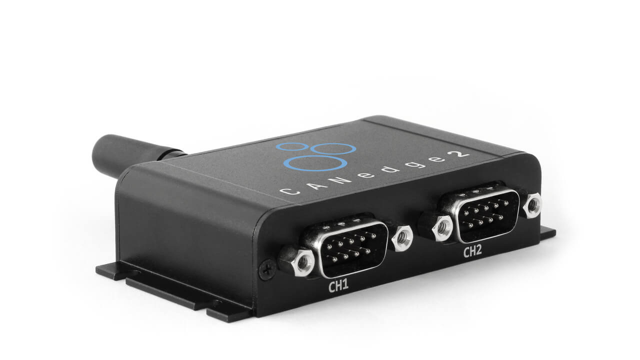
CANedge: UDS data logger
The CANedge1 lets you easily record CAN/UDS data to an 8-32 GB SD card. You can customize what CAN frames to send, incl. custom UDS requests and flow control frames. Data can be processed via free software/API tools. If you also need to offload the recorded data to your own server, the CANedge2 (WiFi) or CANedge3 (3G/4G) automate this upload in the field.
Buy now asammdf Grafana dashboardsCANsub: UDS streaming interface
The CANsub.2/CANsub.4 lets you stream UDS data in real-time via USB or Ethernet - sending UDS request and flow control frames live, and viewing the decoded responses directly in your browser via webCAN with zero software installation. webCAN supports ISO TP reassembly and DBC decoding on the fly - ideal for in-field bidirectional UDS diagnostics.
Buy now webCAN Python API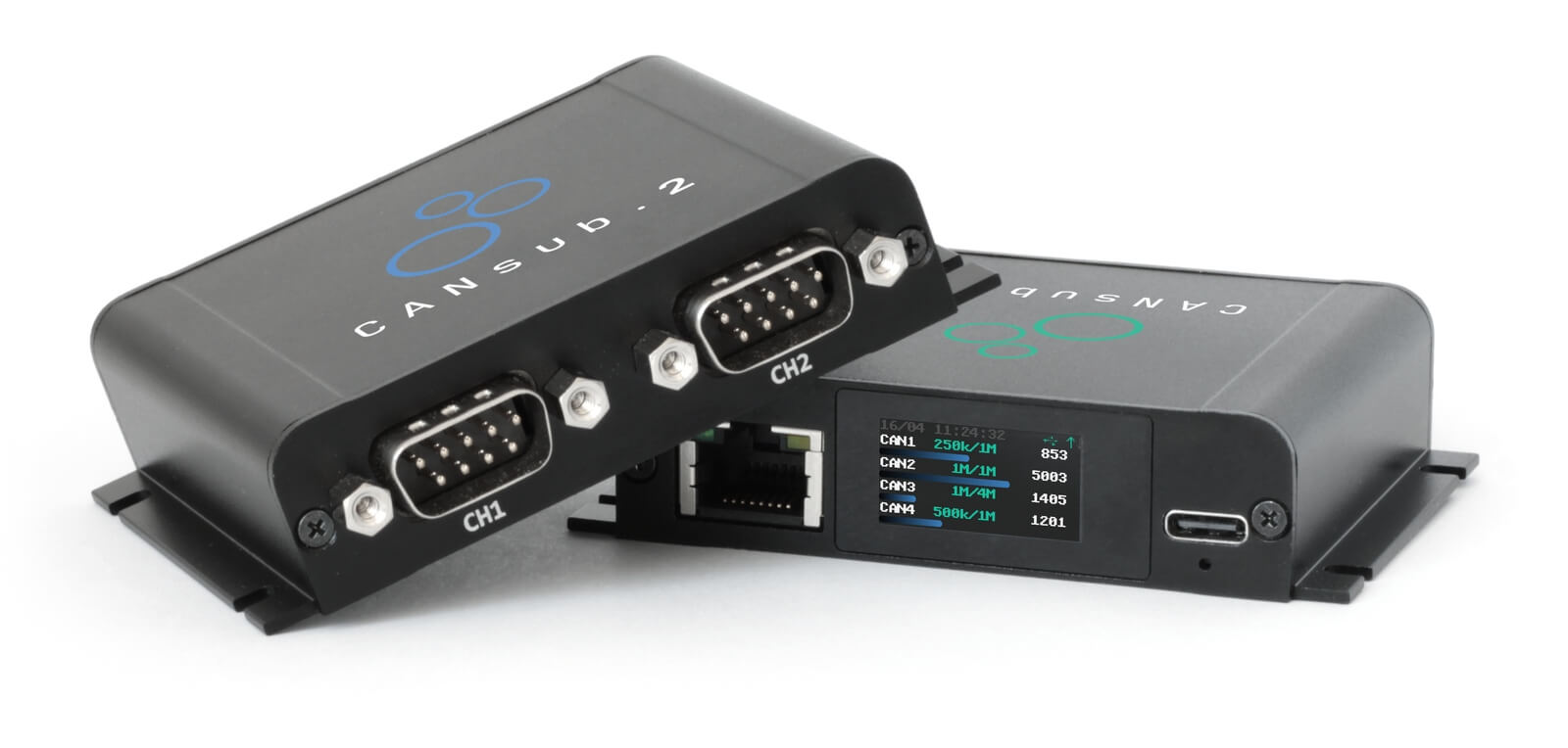
Example 1: Record Single Frame UDS data (Speed via WWH-OBD)
To showcase UDS in practice, we will start with a basic example.
As explained, WWH-OBD is based on UDS - and is mandated in all EU trucks after 2014. As a result, you can typically request speed, RPM, fuel level etc. similarly to how you would do so via OBD2. However, in WWH-OBD (ISO 27145-2), the OBD2 PIDs are replaced by the WWH-OBD DIDs (Data Identifiers).
Specifically, WWH-OBD DIDs match OBD2 PIDs, except that 0xF4 is added in front. For example, the OBD2 PID for Speed is 0x0D - which becomes 0xF40D in the WWH-OBD context.
We can use a CANedge3 to send/receive CAN frames. To request Speed via WWH-OBD, we use the UDS SID 0x22 (Read Data by Identifier) and the DID 0xF40D as below. The resulting payload can be decoded as per our OBD2 intro, resulting in a vehicle speed value of 1 * 0x32 = 50 km/h.

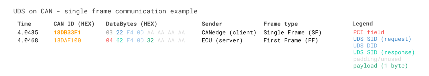
Note how the request is sent with CAN ID 0x18DB33F1. This is the same 29-bit CAN ID that would be used to perform a functionally addressed OBD2 PID request in heavy duty vehicles and can be compared with the 11-bit 0x7DF CAN ID used for OBD2 requests in cars.
The response has CAN ID 0x18DAF100, an example of a physical response ID matching the IDs you'd see in regular OBD2 responses from heavy duty vehicles.
Let's break down the communication flow message payloads:
First, the CANedge2 sends a Single Frame (SF) request:
- The initial 4 bits of the PCI field equal the frame type (0x0 for SF)
- The next 4 bits of the PCI field equal the the length of the request (3 bytes)
- The 2nd byte contains the Service Identifier (SID), in this case 0x22
- The 3rd and 4th bytes contain the DID for Vehicle Speed in WWH-OBD (0xF40D)
- The remaining bytes are padded
In response to this request, the truck responds with a Single Frame (SF) response:
- The 1st byte again reflects the PCI field (now with a length of 4 bytes)
- The 2nd byte is the response SID for Read Data by Identifier (0x62, i.e. 0x22 + 0x40)
- The 3rd and 4th bytes again contain the DID 0xF40D
- The 5th byte contains the value of Vehicle Speed, 0x32
Here we can use the same decoding rules as for ISO/SAE OBD2, meaning that the physical value of Vehicle Speed is simply the decimal form of 0x32 - i.e. 50 km/h. See also our OBD2 PID conversion tool.
If you are familiar with logging OBD2 PIDs, it should be evident that WWH-OBD requests are very similar, except for using the UDSonCAN payload structure for requests/responses.
Example 2: Record multi-frame UDS data (EV SoC%)
In this section, we illustrate how multi frame UDS communication works in the context of CAN ISO-TP.
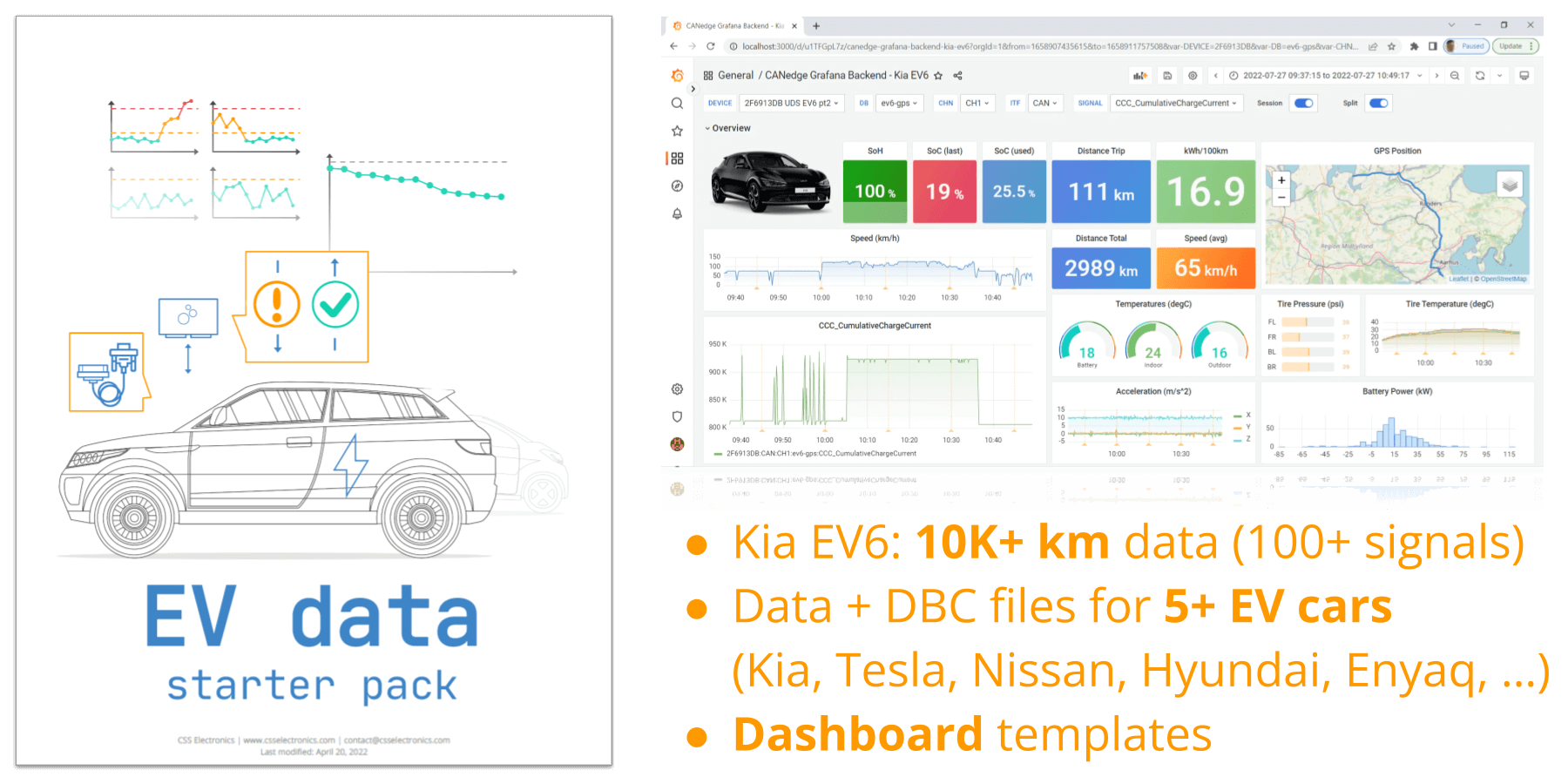
Specifically, we use the CANedge and the UDS SID 0x22 to request the current value of State of Charge (SoC%) from a Kia EV6 electric vehicle (see also our case study).
First, the CANedge is configured to send two CAN frames:
- A Single Frame (SF) request (period: 5000 ms, delay: 0 ms)
- A Flow Control (FC) frame (period: 5000 ms, delay: 100 ms)
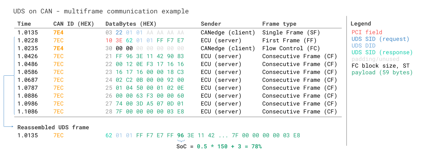
Below is a subset of the resulting communication flow:
The CANedge can be used to request UDS data from e.g. the Kia EV6 for visualization - learn more in our telematics dashboards intro.
In the following we explore this communication between the CANedge and ECU in detail.
First of all, the initial Single Frame (SF) request is constructed via the same logic as in our previous example - containing the PCI field, the SID 0x22 and the DID. In this case, we use the DID 0x0101.
In response to the initial SF request, the targeted ECU sends a First Frame (FF) response:
- The initial 4 bits equal the frame type (0x1 for FF)
- The next 12 bits equal the data payload size, in this case 62 bytes (0x03E)
- The 3rd byte is the response SID for Read Data by Identifier (0x62, i.e. 0x22 + 0x40)
- The 4th and 5th bytes contain the Data Identifier (DID) 0x0101
- The remaining bytes contain the initial part of the data payload for the DID 0x0101
Following the FF, the tester tool now sends the Flow Control (FC) frame:
- The initial 4 bits equal the frame type (0x3 for FC)
- The next 4 bits specifies that the ECU should "Continue to Send" (0x0)
- The 2nd byte sets remaining frames to be sent without flow control or delay
- The 3rd byte sets the minimum consecutive frame separation time (ST) to 0
Once the ECU receives the FC, it sends the remaining Consecutive Frames (CF):
- The initial 4 bits equal the frame type (0x2 for CF)
- The next 4 bits equal the index counter, incremented from 1 up to 8 in this case
- The remaining 7 bytes of each CF contain the rest of the payload for the DID
Part of the information used here is proprietary. In particular, it is generally not known what Data Identifier (DID) to use in order to request e.g. State of Charge from a given electric vehicle, unless you're the vehicle manufacturer (OEM). Further, as explained in the next section, it is not known how to decode the response payload.
However, various online resources exist e.g. on github, where enthusiasts create open source databases for specific parameters and certain cars (based on reverse engineering). The information we use for this specific communication is taken from one such database. We provide a collection of such DBC files in our EV data pack.
In this case we use the CAN ID 0x7E4 to request data from a specific ECU, which in turn responds with CAN ID 0x7EC. This is known as a physically addressed request.
In contrast, functionally addressed request would use the CAN ID 0x7DF (or 0x18DB33F1 in heavy duty vehicles).
Generally, request/response CAN IDs are paired (as per the table below) and you can identify the physical request ID corresponding to a specific physical response ID by subtracting the value 8 from the response ID. In other words, if an ECU responds via CAN ID 0x7EC, the physical request ID targeting that ECU would be 0x7E4 (as in our EV example).
Since you may not know what address to target initially, you can in some cases start by sending out a functional request using the CAN ID 0x7DF, in which case the relevant ECU should provide a positive First Frame response if the initial request payload is structured correctly. In some vehicles, you may be able to also send the subsequent Flow Control frame using the same CAN ID, 0x7DF, in order to trigger the ECU to send the remaining Consecutive Frames. However, some implementations may require that you instead utilize the physical addressing request ID for the Flow Control frame.
Implementing a request structure with dynamically updating CAN IDs may be difficult. If you're the manufacturer, you will of course know the relevant CAN IDs to use for sending physically addressed service requests. If not, you may perform an analysis using e.g. a CAN bus interface to identify what response CAN IDs appear when sending functionally addressed service requests - and using this information to construct your configuration.
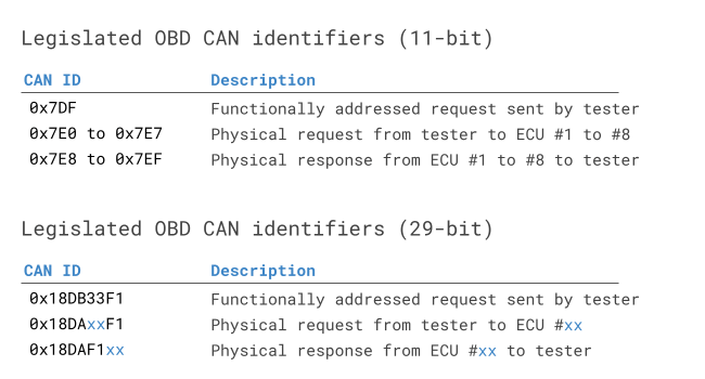
On a separate note, ISO 15765-4 states that enhanced diagnostics requests/responses may utilize the legislated OBD2 CAN ID range as long as it does not interfere - which is what we are seeing in this specific Hyundai Kona example where the IDs 0x7EC/0x7E4 are used for proprietary data.
See also the table from ISO 15765-4 for an overview of the legislated OBD CAN identifiers for use in functional and physical OBD PID requests:
In the above example, we generally focus on the sequence of CAN frames. The sequence is important: For example, if your tester tool sends the Flow Control frame before receiving the First Frame, the Flow Control frame will either be ignored (thus not triggering the Consecutive Frames) or cause an error.
However, in addition to this, certain timing thresholds will also need to be satisfied. For example, if your tester tool receives the First Frame from an ECU of a multi frame response, the ECU will 'time out' if the Flow Control frame is not sent within a set timeperiod.
As a rule of thumb, you should configure your tester (e.g. the CANedge) so that the Flow Control frame is always sent after the First Frame response is received from the ECU (typically this happens within 10-50 ms from sending the initial request) - but in a way so that it is sent within a set time after receiving the First Frame (e.g. within 0-50 ms). For details on this, feel free to contact us.
How to decode multi-frame UDS data?
We've now shown how you can request/record a multi-frame UDS response to collect proprietary ECU sensor data. In order to extract 'physical values' like State of Charge, you need to know how to interpret the response CAN frames.
As explained, the 'decoding' information is typically proprietary and only known to the OEM. However, the information can be found for many EVs via online resources. We also collect this information in our free EV data pack for several brands.
For the Kia EV6 example, we create a DBC file using the online information. The DBC uses 'extended multiplexing' to distinguish between different UDS SID and DID values.
Download our EV data pack to get EV sample data and DBC files

Normally, we would now use the DBC to decode the raw CAN frames into physical values as explained in our intro to CAN bus.
However, to do so we must first reassemble the segmented CAN frames.
By performing reassembly in the EV6 trace example, we get a single 'CAN frame' with ID 0x7EC and 62 data bytes. Note that we remove the ISO-TP fields during the reassembly.
In practice, you will use software/API tools that support ISO-TP and DBC decoding. The CANedge offers multiple options:
- MF4 converters: Load your data in e.g. Vector tools
- MF4 decoders: Create decoded Parquet data lakes
- Python API: Use python-can to handle ISO-TP and decoding
In our example, the Kia EV6 DBC specifies that SoC is found in the 8th byte and should be decoded with a scaling factor of 0.5 and an offset of 3. This results in a SoC of 78%.

You can use the MF4 decoders for e.g. dashboard visualization of UDS data
Example 3: Record the Vehicle Identification Number (VIN)
The Vehicle Identification Number (aka VIN, chassis number, frame number) is a unique identifier code used for road vehicles. The number has been standardized and legally required since the 1980s - for details see the VIN page on Wikipedia.

A VIN consists of 17 ASCII characters and can be extracted on-request from a vehicle. This is useful in e.g. data logging or telematics use cases where a unique identifier is required for association with e.g. CAN bus log files.
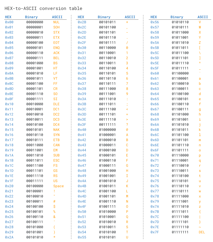
CAN data bytes can be converted from HEX to ASCII via tables, online HEX to ASCII converters, Python packages etc.
For example, the byte 0x47 corresponds to the letter "G".
Since a VIN is 17 bytes (17 ASCII characters) long, it does not fit into a single CAN frame, but has to be extracted via a multi frame diagnostic request/response as in Example 2. Further, the VIN is extracted differently depending on the protocol used.
Below we provide three examples on how to record the VIN.
3.1: How to record the VIN via OBD2 (SAE J1979)
To extract the Vehicle Identification Number from e.g. a passenger car using OBD2 requests, you use Service 0x09 and the PID 0x02:
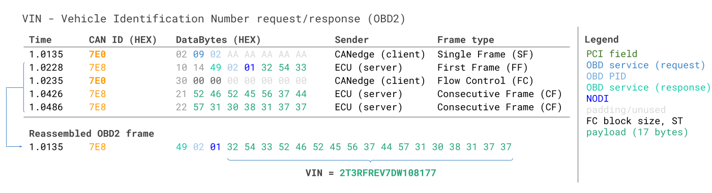
The logic of the frame structure is identical to Example 2, with the tester tool sending a Single Frame request with the PCI field (0x02), request service identifier (0x09) and data identifier (0x02).
The vehicle responds with a First Frame containing the PCI, length (0x014 = 20 bytes), response SID (0x49, i.e. 0x09 + 0x40) and data identifier (0x02). Following the data identifier is the byte 0x01 which is the Number Of Data Items (NODI), in this case 1 (see SAE J1979 or ISO 15031-5 for details).
The remaining 17 bytes equal the VIN and can be translated from HEX to ASC via the methods previously discussed.
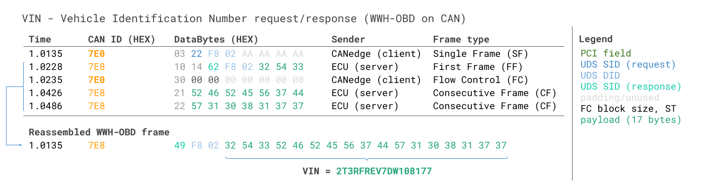
3.2: How to record the VIN via UDS (ISO 14229-2)
To read the Vehicle Identification Number via UDS, you can use the UDS SID 0x22 and the DID 0xF190:
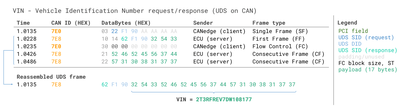
As evident, the request/response communication flow looks similar to the OBD2 case above. The main changes relate to the use of the UDS service 0x22 instead of the OBD2 service 0x09 - and the use of the 2-byte UDS DID 0xF190 instead of the 1 byte OBD2 PID 0x02. Further, the UDS response frame does not include the Number of Data Items (NODI) field after the DID, in contrast to what we saw in the OBD2 case.
3.3: How to record the VIN via WWH-OBD (ISO 27145-3)
If you need to request the Vehicle Identification Number from an EU truck after 2014, you can use the WWH-OBD protocol. The structure is identical to the UDS example, except that WWH-OBD specifies the use of the DID 0xF802 for the VIN.
Example 4: Record Diagnostic Trouble Codes (WWH-OBD)
Below shows a request/response trace for reading 6 x Diagnostic Trouble Codes (DTCs) via WWH-OBD:
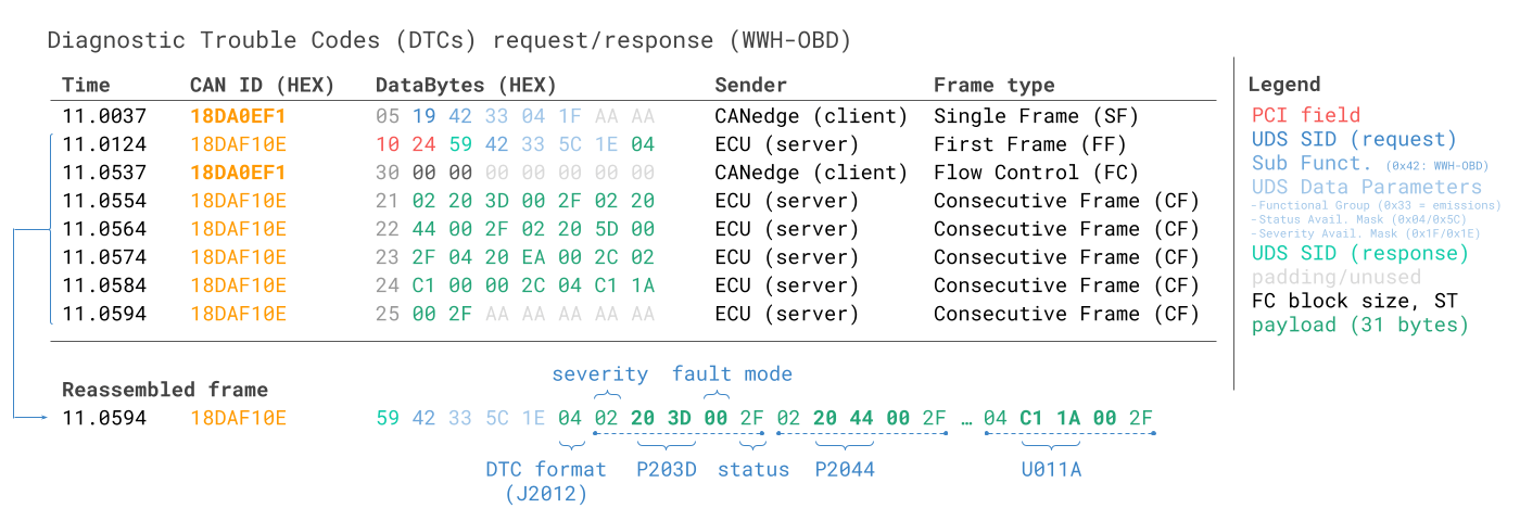
The WWH-OBD DTC request/response flow uses service 0x19 and sub function byte 0x42. If we compare vs. our UDS message section, this indeed corresponds to requesting Diagnostic Trouble Codes via UDS, specifically for WWH-OBD. The remaining 3 bytes in the request message are UDS data parameters, essentially specifying further configuration details of the request. For example, 0x33 is used to specify that we wish to request emissions related fault codes, while the masks allow us to control what type of error codes we wish to request.
In the response message, the 'format identifier' 0x04 implies that we should interpret the DTCs as per SAE J2012 (rather than e.g. as per SAE J1939-73). As evident, the response includes 5 bytes for each DTC, of which the middle 3 bytes equal the actual DTC. The 1st byte out of the five reflects the 'severity' of the DTC. As per J2012, the next two data bytes reflect the fault code, which is P203D aka 'Reductant Level Sensor Circuit High'. The next byte reflects the fault mode/type, in this case 0x00. Finally, the status value 0x2F informs of the status of the DTC (e.g. whether it is pending, confirmed, potential, ...). The 5-byte section is then repeated for each of the six DTCs.
It can be useful to compare this trace vs. our OBD2 DTC trace example. In both cases, the ECU returns 6 DTCs, but while the OBD2 example returns 2-byte DTCs, the WWH-OBD example returns 3-byte DTCs (wrapped in segments of 5 bytes). In this example, the 'format identifier' 0x04 means that the DTCs should be interpreted as per J2012 (i.e. like OBD2 fault codes). You can use our OBD DTC converter to lookup the fault code and name based on the raw hex data bytes.
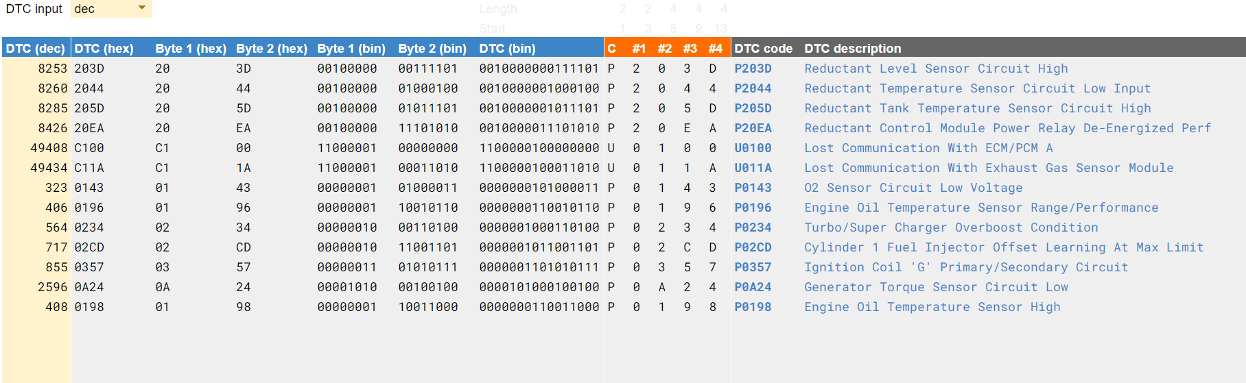 The OBD DTC
converter
lets you convert raw data to OBD fault codes
The OBD DTC
converter
lets you convert raw data to OBD fault codes
UDS data logging - applications
In this section, we outline example use cases for recording UDS data.

UDS telematics for prototype electric vehicles
As an OEM, you may need to get data on various sensor parameters from prototype EVs while they are operating in the field. Here, the CANedge3 can be deployed to request data on e.g. state of charge, state of health, temperatures and more by transmitting UDS request frames and flow control frames periodically. The data is combined with the internally generated GPS/IMU data and sent via a 3G/4G to your own cloud server for analysis via Vector tools, Python or MATLAB.
Training a predictive maintenance model
If you're looking to implement predictive maintenance across fleets of heavy duty vehicles, the first step is typically to "train your model". This requires large amounts of training data to be collected, including both sensor data (speed, RPM, throttle position, tire pressures etc) and "classification results" (fault / no fault). One way to obtain the latter is by periodically requesting diagnostic trouble codes from the vehicle, providing you with log files that combine both types of data over time. You can use the CANedge1 to collect this data offline onto SD cards, or the CANedge2/CANedge3 to automatically offload the data - e.g. when the vehicles return to stationary WiFi routers in garages or when 3G/4G coverage is available.


Real-time UDS analysis on the OEM bench
As an OEM engineer bringing up a new ECU or diagnosing an intermittent fault, you may need to interact with the ECU bidirectionally - reading DIDs, clearing DTCs, triggering routines and even flashing firmware. With the CANsub.2/CANsub.4 connected to the ECU via USB or Ethernet, you can construct UDS request and flow control transmit sequences in webCAN's DBC encoder, stream the responses live with ISO TP reassembly and DBC decode them on the fly into named signals - ideal for iterative bench work where you need to see results immediately. For automated UDS sequences and scripting, the same data can be accessed via the CANsub Python API.
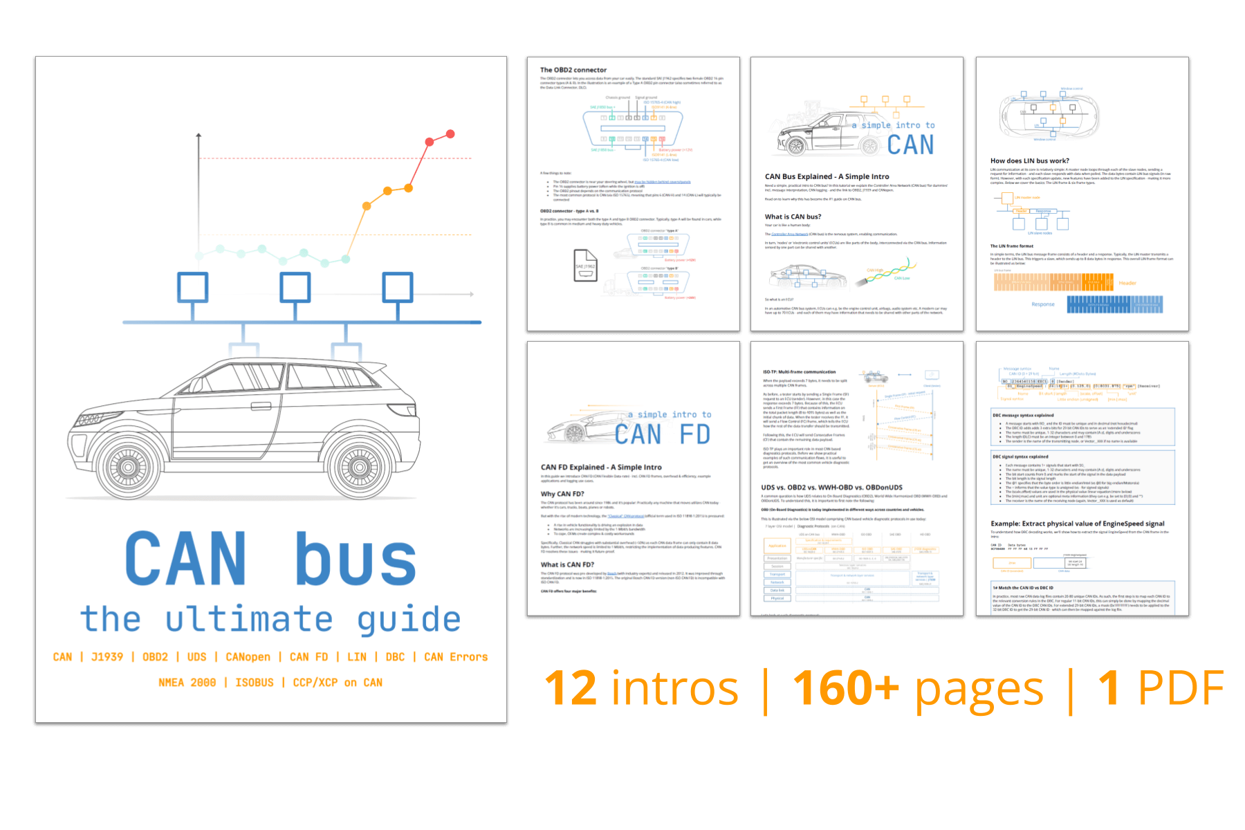
For more intros, see our guides section - or download the 'Ultimate Guide' PDF.
Ready to log/stream UDS data?
Get your CANedge/CANsub today!