CAN Bus Errors Explained - A Simple Intro [2026]

Need a practical intro to CAN bus errors?
In this tutorial you will learn about the basics of CAN error handling, the 5 CAN bus error types, the CAN error frame and CAN node error states.
To get practical, we will also generate & record CAN errors in 6 experiments and discuss how to troubleshoot CAN bus errors.
In this article

What are CAN bus errors?
As explained in our simple intro to CAN bus, the Controller Area Network is today the de facto standard across automotives and industrial automation systems.
A core benefit is the robustness of CAN, making it ideal for safety critical applications. Here, it is worth noting:
Error handling is vital to the robustness of CAN.
CAN bus errors can occur for several reasons - faulty cables, noise, incorrect termination, malfunctioning CAN nodes etc. Identifying, classifying and resolving such CAN errors is key to ensuring the continued performance of the overall CAN system.
In particular, error handling identifies and rejects erroneous messages, enabling a sender to re-transmit the message. Further, the process helps identify and disconnect CAN nodes that consistently transmit erroneous messages.
Understanding CAN errors is vital in CAN bus diagnostics.

How does CAN error handling work?
Error handling is a built-in part of the CAN standard and every CAN controller. In other words, every CAN node handles fault identification and confinement identically. Below we've made a simple illustrative example:

- CAN node 1 transmits a message onto the CAN bus - and reads every bit it sends
- In doing so, it discovers that one bit that was sent dominant was read recessive
- This is a 'Bit Error' and node 1 raises an Active Error Flag to inform other nodes
- In practice, this means that node 1 sends a sequence of 6 dominant bits onto the bus
- In turn, the 6 dominant bits are seen as a 'Bit Stuffing Error' by other nodes
- In response, nodes 2 and 3 simultaneously raise an Active Error Flag
- This sequence of raised error flags comprise part of a 'CAN error frame'
- CAN node 1, the transmitter, increases its 'Transmit Error Counter' (TEC) by 8
- CAN nodes 2 and 3 increase their 'Receive Error Counter' (REC) by 1
- CAN node 1 automatically re-transmits the message - and now succeeds
- As a result, node 1 reduces its TEC by 1 and nodes 2 and 3 reduce their REC by 1
The example references a number of concepts that we will detail shortly: Error frames, error types, counters and states.

The CAN bus error frame
In the illustrative example, the CAN nodes 'raise Active Error Flags', thus creating an 'error frame' in response to detecting a CAN error.
To understand how this works, let us first look at a "normal" CAN frame (without errors):
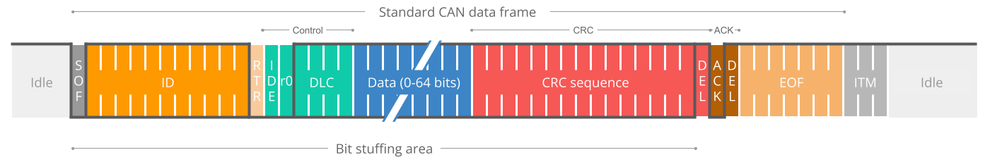
CAN bus bit stuffing
Notice that we highlighted 'bit stuffing' across the CAN frame.
Bit stuffing is a subtle, but vital part of the CAN standard. Basically it states that whenever a CAN node sends five bits of the same logic level (dominant or recessive), it must send one bit of the opposite level. This extra bit is automatically removed by the receiving CAN nodes. This process helps ensure continuous synchronisation of the network.
As per the previous example, when CAN node 1 detects an error during the transmission of a CAN message, it immediately transmits a sequence of 6 bits of the same logic level - also referred to as raising an Active Error Flag.
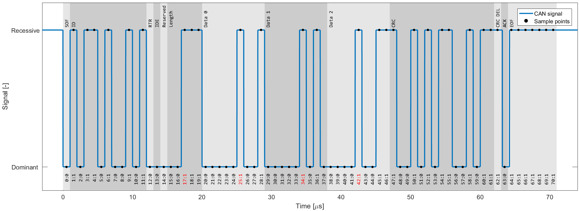
If we measure the transmission of a CAN frame via an oscilloscope and digitize the result, we can also see the stuff bits in practice (see the red timestamp marks):


Active Error Flags
As we just learned, such a sequence is a violation of the bit stuffing rule - aka a 'Bit Stuffing Error'. Further, this error is visible to all CAN nodes on the network (in contrast to the 'Bit Error' that resulted in this error flag being raised). Thus, the raising of error flags can be seen as a way of "globalizing" the discovery of an error, ensuring that every CAN node is informed.
Note that the other CAN nodes will see the Active Error Flag as a Bit Stuffing Error. In response they also raise an Active Error Flag.
As we'll explain shortly, it is important to distinguish between the error flags. In particular, the first error flag (from the 'discovering' node) is often referred to as a 'primary' Active Error Flag, while the error flags of subsequent 'reacting' nodes are referred to as the 'secondary' Active Error Flag(s).
3 CAN error frame examples
Let's look at three example scenarios:
Example 1: 6 bits of error flags
Here, all CAN nodes simultaneously discover that an error exists in a CAN message and raise their error flags at the same time.
The result is that the error flags all overlap and the total sequence of dominant bits lasts for 6 bits in total. All CAN nodes will in this case consider themselves the 'discovering' CAN nodes.
This type of simultaneous discovery is less common in practice. However, it could e.g. happen as a result of Form Errors (such as a CRC delimiter being dominant instead of recessive), or if a CAN transmitter experiences a bit error during the writing of a CRC field.


Example 2: 12 bits of error flags
Here, CAN node 1 transmits a dominant bit, but reads it as recessive - meaning that it discovers a Bit Error. It immediately transmits a sequence of 6 dominant bits.
The other nodes only discover the Bit Stuffing Error after the full 6 bits have been read, after which they simultaneously raise their error flags, resulting in a subsequent sequence of 6 dominant bits - i.e. 12 in total.
Example 3: 9 bits of error flags
Here, CAN node 1 has already transmitted a sequence of 3 dominant bits when it discovers a Bit Error and begins sending 6 dominant bits.
Once halfway through the primary Active Error Flag, nodes 2 and 3 recognize the Bit Stuffing Error (due to the 3 initial dominant bits being followed by another 3 dominant bits) and they begin raising their error flags. The result is that the sequence of dominant bits from error flags becomes 9 bit long.

The above logic of raising error flags is reflected in what we call an 'active' CAN error frame.

Note in particular how the secondary error flags raised by various nodes overlap each other - and how the primary and secondary flags may overlap as well. The result is that the dominant bit sequence from raised error flags may be 6 to 12 bits long.
This sequence is always terminated by a sequence of 8 recessive bits, marking the end of the error frame.
In practice, the active error frame may "begin" at different places in the erroneous CAN frame, depending on when the error is discovered. The result, however, will be the same: All nodes discard the erroneous CAN frame and the transmitting node can attempt to re-transmit the failed message.
Passive Error Flags
If a CAN node has moved from its default 'active' state to a 'passive' state (more on this shortly), it will only be able to raise so-called 'Passive Error Flags'. A Passive Error Flag is a sequence of 6 recessive bits as seen below.
In this case it's relevant to distinguish between a Passive Error Flag raised by a transmitting node and a receiving node.

Example 4: Transmitter is Error Passive
As shown in the illustration (Example 4), if a transmitter (such as CAN node 1 in our example) raises a Passive Error Flag (e.g. in response to a Bit Error), this will correspond to a consecutive sequence of 6 recessive bits.
This is in turn detected as a Bit Stuffing Error by all CAN nodes. Assuming the other CAN nodes are still in their Error Active state, they will raise Active Error Flags of 6 dominant bits. In other words, a passive transmitter can still "communicate" that a CAN frame is erroneous.
Example 5: Receiver is Error Passive
In contrast, if a receiver raises a Passive Error Flag this is in practice "invisible" to all other CAN nodes on the bus (as any dominant bits win over the sequence of recessive bits) - see also Example 5.
Effectively, this means that an Error Passive receiver no longer has the ability to destroy frames transmitted by other CAN nodes.

CAN error types
Next, let us look at what errors may cause CAN nodes to raise error flags.
The CAN bus protocol specifies 5 CAN error types:
- Bit Error [Transmitter]
- Bit Stuffing Error [Receiver]
- Form Error [Receiver]
- ACK Error (Acknowledgement) [Transmitter]
- CRC Error (Cyclic Redundancy Check) [Receiver]
We've already looked at Bit Errors and Bit Stuffing Errors briefly, both of which are evaluated at the bit level. The remaining three CAN error types are evaluated at the message level.
Below we detail each error type:


#1 Bit Error
Every CAN node on the CAN bus will monitor the signal level at any given time - which means that a transmitting CAN node also "reads back" every bit it transmits. If the transmitter reads a different data bit level vs. what it transmitted, the transmitter detects this as a Bit Error.
If a bit mismatch occurs during the arbitration process (i.e. when sending the CAN ID), it is not interpreted as a Bit Error. Similarly, a mismatch in the acknowledgement slot (ACK field) does not cause a Bit Error as the ACK field specifically requires a recessive bit from the transmitter to be overwritten by a dominant bit from a receiver.

#2 Bit Stuffing Error
As explained, bit stuffing is part of the CAN standard. It dictates that after every 5 consecutive bits of the same logical level, the 6th bit must be a complement. This is required to ensure the on-going synchronization of the network by providing rising edges. Further, it ensures that a stream of bits are not mis-interpreted as an error frame or as the interframe space (7 bit recessive sequence) that marks the end of a message. All CAN nodes automatically remove the extra bits.
If a sequence of 6 bits of the same logical level is observed on the bus within a CAN message (between the SOF and CRC field), the receiver detects this as a Bit Stuffing Error aka Stuff Error.

#3 Form Error
This message-level check utilises the fact that certain fields/bits in the CAN message must always be of a certain logical level. Specifically the 1-bit SOF must be dominant, while the entire 8-bit EOF field must be recessive. Further, the ACK and CRC delimiters must be recessive. If a receiver finds that any of these are bits are of an invalid logical level, the receiver detects this as a Form Error.

#4 ACK Error (Acknowledgement)
When a transmitter sends a CAN message, it will contain the ACK field (Acknowledgement), in which the transmitter will transmit a recessive bit. All listening CAN nodes are expected to send a dominant bit in this field to verify the reception of the message (regardless of whether the nodes are interested in the message or not). If the transmitter does not read a dominant bit in the ACK slot, the transmitter detects this as an ACK Error.

#5 CRC Error (Cyclic Redundancy Check)
Every CAN message contains a Cyclic Redundancy Checksum field of 15 bits. Here, the transmitter has calculated the CRC value and added it to the message. Every receiving node will also calculate the CRC on their own. If the receiver's CRC calculation does not match the transmitter's CRC, the receiver detects this as a CRC Error.
CAN node states & error counters
As evident, CAN error handling helps destroy erroneous messages - and enables CAN nodes to retry the transmission of erroneous messages.
This ensures that short-lived local disturbances (e.g. from noise) will not result in invalid/lost data. Instead, the transmitter attempts to re-send the message. If it wins arbitration (and there are no errors), the message is successfully sent.
However, what if errors are due to a systematic malfunction in a transmitting node? This could trigger an endless loop of sending/destroying the same message - jamming the CAN bus.
This is where CAN node states and error counters come in.


In short, the purpose of CAN error tracking is to confine errors by gracefully reducing the privileges of problematic CAN nodes.
Specifically, let's look at the three possible states:
- Error Active: This is the default state of every CAN node, in which it is able to transmit data and raise 'Active Error Flags' when detecting errors
- Error Passive: In this state, the CAN node is still able to transmit data, but it now raises 'Passive Error Flags' when detecting errors. Further, the CAN node now has to wait for an extra 8 bits (aka Suspend Transmission Time) in addition to the 3 bit intermission time before it can resume data transmission (to allow other CAN nodes to take control of the bus)
- Bus Off: In this state, the CAN node disconnects itself from the CAN bus and can no longer transmit data or raise error flags
Every CAN controller keeps track of its own state and acts accordingly. CAN nodes shift state depending on the value of their error counters. Specifically, every CAN node keeps track on a Transmit Error Counter (TEC) and Receive Error Counter (REC):
- A CAN node enters the Error Passive state if the REC or TEC exceed 127
- A CAN node enters the Bus Off state if the TEC exceeds 255
How do the error counters change?
Before we get into the logic of how error counters are increased/reduced, let us revisit the CAN error frame as well as the primary/secondary error flags.
As evident from the CAN error frame illustration, a CAN node that observes a dominant bit after its own sequence of 6 dominant bits will know that it raised a primary error flag. In this case, we can call this CAN node the 'discoverer' of the error.
At first, it might sound positive to have a CAN node that repeatedly discovers errors and reacts promptly by raising an error flag before other nodes. However, in practice, the discoverer is typically also the culprit causing errors - and hence it is punished more severely as per the overview.

There are some additions/exceptions to the above rules.
Most are pretty straight-forward based on our previous illustrative example. For example, it seems clear that CAN node 1 would increase the TEC by 8 as it discovers the Bit Error and raises an error flag. The other nodes in this case increase their REC by 1.
This has the intuitive consequence that the transmitting node will quickly reach the Error Passive and eventually Bus Off states if it continuously produces faulty CAN messages - whereas the receiving nodes do not change state.
The case where a receiver raises the primary error flag may seem counter-intuitive. However, this could for example be the case if a receiver CAN node is malfunctioning in a way that causes it to incorrectly detect errors in valid CAN messages. In such a case, the receiver would raise the primary error flag, effectively causing an error. Alternatively, it can happen in cases where all CAN nodes simultaneously raise error flags.
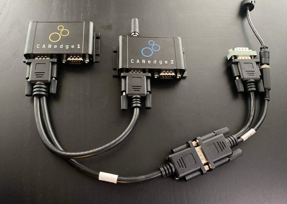
CAN/LIN data & error logger
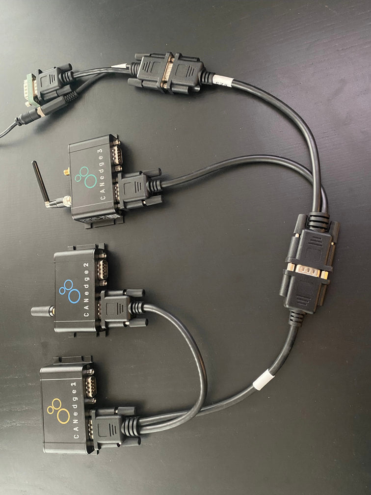
The CANedge1 lets you easily record data from 2 x CAN/LIN buses to an 8-32 GB SD card - incl. support for logging CAN/LIN errors. Simply connect it to e.g. a car or truck to start logging - and decode the data via free software/APIs.
Further, the CANedge2 (WiFi) and CANedge3 (3G/4G) let you push data to your own server - and update devices over-the-air.
learn about the CANedgeExamples: Generating & logging error frames
We have now covered the theoretical basics of CAN errors and CAN error handling. Next, let us look at generating and logging CAN bus faults in practice. For this we will use a couple of CANedge devices - and for some tests a PCAN-USB device.
Tip: Download the MF4 data for the tests to view the data in asammdf or CANalyzer.
download dataTest #1: No CAN bus errors
As a benchmark, we start with a test involving no CAN bus errors. Here, a CANedge2 'transmitter' sends data to CANedge1 'receiver' - and both log CAN bus errors.
By loading the MF4 log file in the asammdf GUI we verify that no CAN errors occurred during this test, which is to be expected.
Test #2: Removing the CAN bus terminal resistor
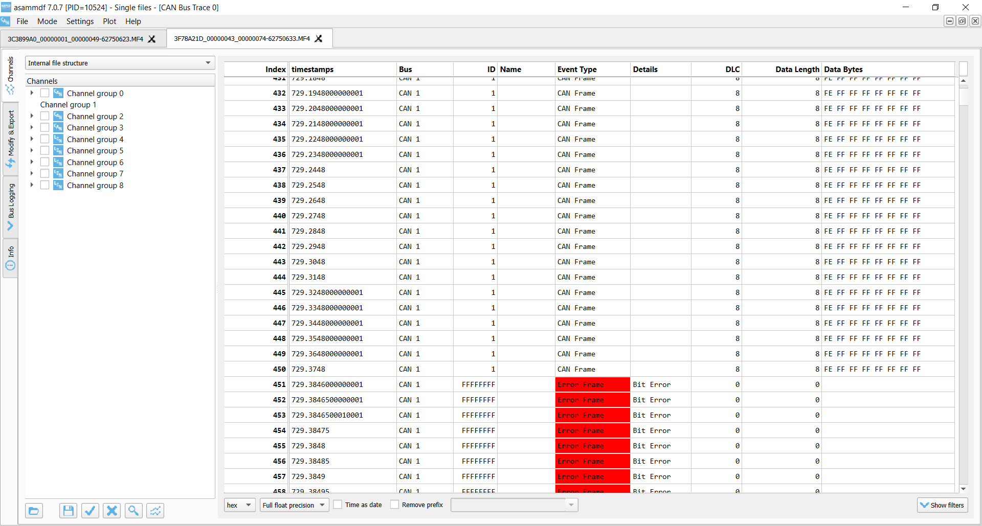
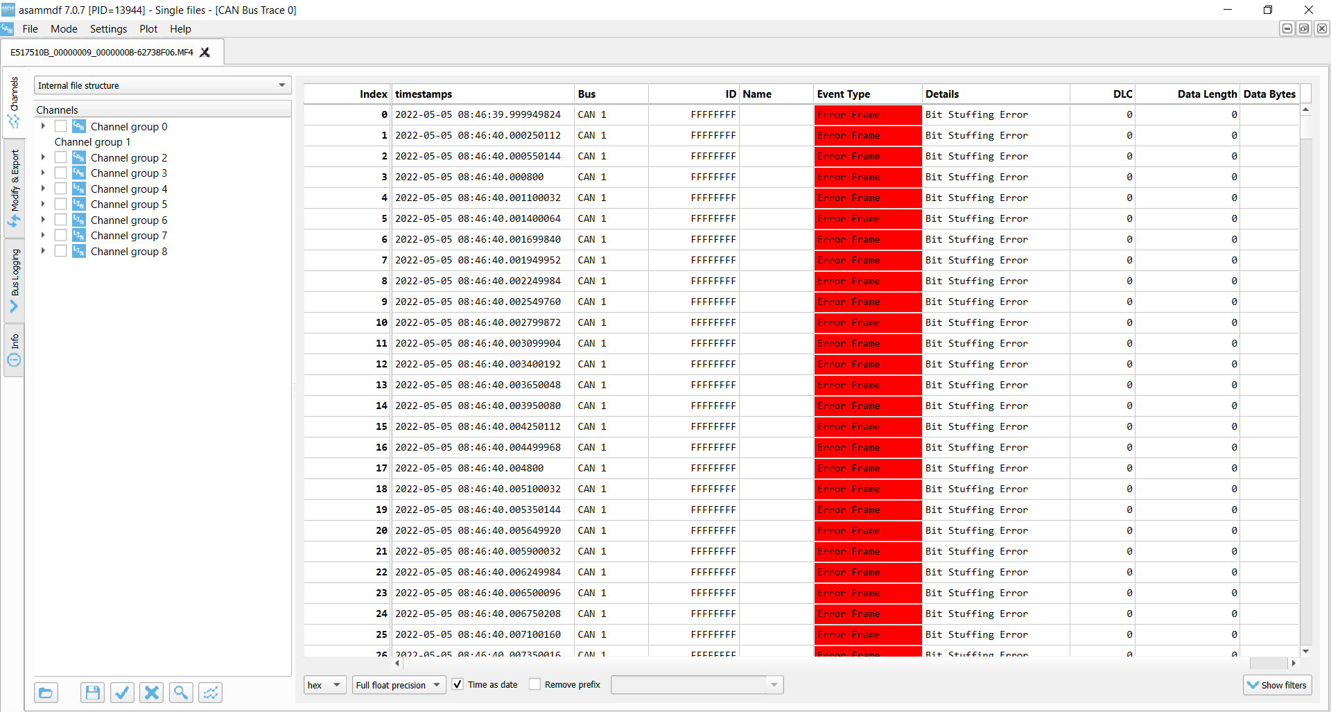
In this test, we remove the CAN termination in the middle of a log session. This effectively corresponds to immediately setting the bit level to dominant. As a result, the CANedge2 transmitter immediately starts logging Bit Errors (which occur when it attempts to transmit a recessive bit, but reads a dominant bit). The CANedge1 Receiver logs Bit Stuffing Errors as it detects 6 consecutive dominant bits. These errors are recorded until the termination is added again.
Lack of termination is rarely a practical CAN bus issue if you're recording data from a vehicle, machine etc. However, it's a common problem when working with 'test bench' setups. Here, the lack of termination may cause confusion as it can be difficult to distinguish from an inactive CAN bus. If in doubt, enabling error frame logging on the CANedge can be useful in troubleshooting.
 Transmitter Bit Errors
 Receiver Bit Stuffing Errors
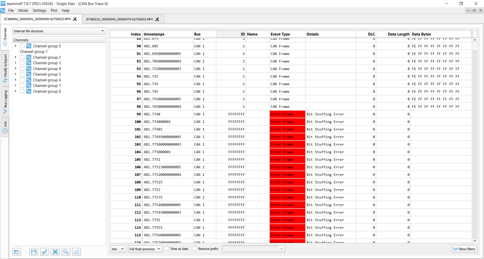
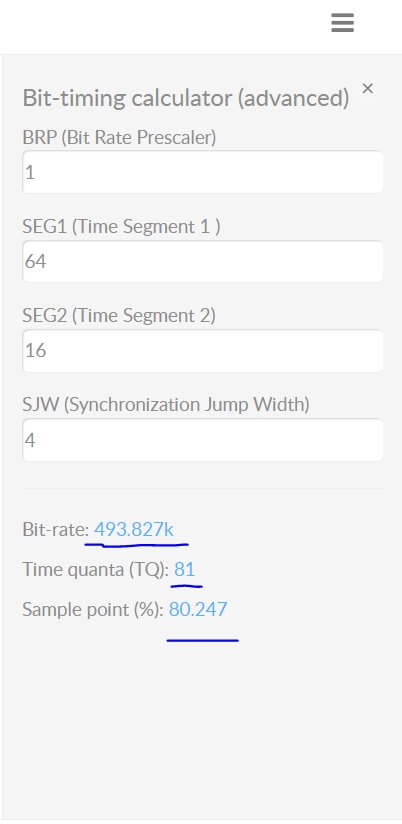
Test #3: Setting an incorrect baud rate
In this test we configure the CANedge1 receiver node to have a baud rate of 493.827K vs. the baud rate of the transmitter of 500K. This is a fairly extreme difference and results in ACK Errors for the transmitter and Bit Stuffing Errors for the receiver.
In more realistic scenarios, smaller differences in the baud rate configuration of various nodes may cause intermittent error frames and thus message loss.
This example is rather extreme. However, in practice we have sometimes seen CAN buses that use standard bit rates (250K, 500K, ...), but with specific bit timing settings that differ from the ones that are typically recommended (and hence used by the CANedge). This will not lead to a complete shut-down of the communication, but rather periodic frame loss of a few percentages. To resolve this, you can construct an 'advanced bit rate' in the CANedge configuration, essentially setting up the bit-timing to better match the CAN bus you're logging from.
 Transmitter ACK Error
 Receiver Bit Stuffing Errors
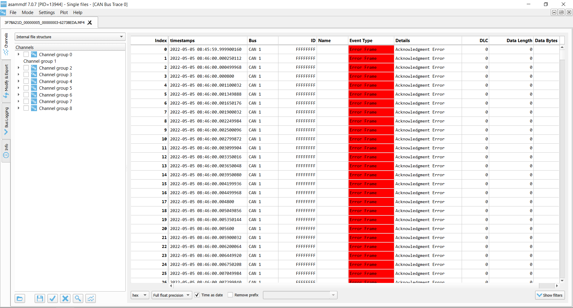
Test #4: Removing the acknowledging CAN node
In this test, we use three CANedge units configured as follows:
- CANedge1: Configured to acknowledge data
- CANedge2: Configured in 'silent mode' (no acknowledgement)
- CANedge3: Configured to transmit a CAN frame every 500 ms
In the default setup, data is transmitted by the CANedge3 onto the CAN bus and recorded with no errors. However, if we remove the CANedge1 from the bus there are no longer any CAN nodes to acknowledge the frames sent by the transmitter.
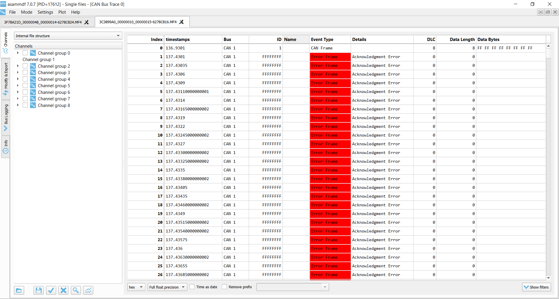
As a result, the transmitter detects ACK Errors. In response, it increases its Transmit Error Counter and raises Active Error Flags onto the CAN bus. These are in turn recorded by CANedge2 (which silently monitors the bus) as Form Errors.
This is due to the fact that the transmitter raises them upon identifying the lack of a dominant bit in the ACK slot. As soon as a dominant bit is observed by the receiver in the subsequent EOF field (which should be recessive), a Form Error is detected.
As evident, the transmitter broadcasts 16 Active Error Flags as its TEC is increased from 0 to 16 x 8 = 128. The transmitter has now exceeded the threshold of a TEC of 127 and enters Error Passive mode. As a result, the transmitter still experiences ACK Errors, but now only raises Passive Error Flags (not visible to the receiver). At this point, the transmitter keeps attempting to transmit the same frame - and the receiver keeps recording this retransmission sequence.
This type of error is one we often encounter in our support tickets. Specifically, users may be trying to use our CAN loggers to record data from a single CAN node (such as a sensor-to-CAN module like our CANmod). If they decide to enable 'silent mode' on the CANedge in such an installation, no CAN nodes will acknowledge the single CAN node broadcasting data - and the result will either be empty log files, or log files filled with retransmissions of the same CAN frame (typically at very high frequency).
 Transmitter ACK Errors
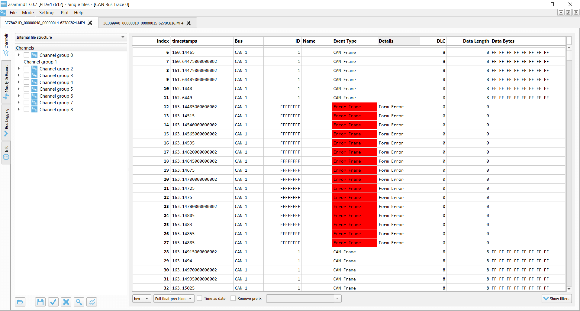 Receiver Form Errors
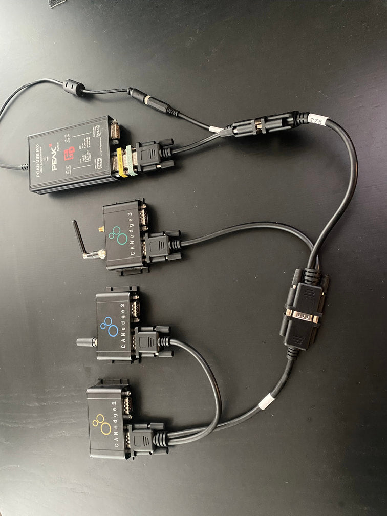
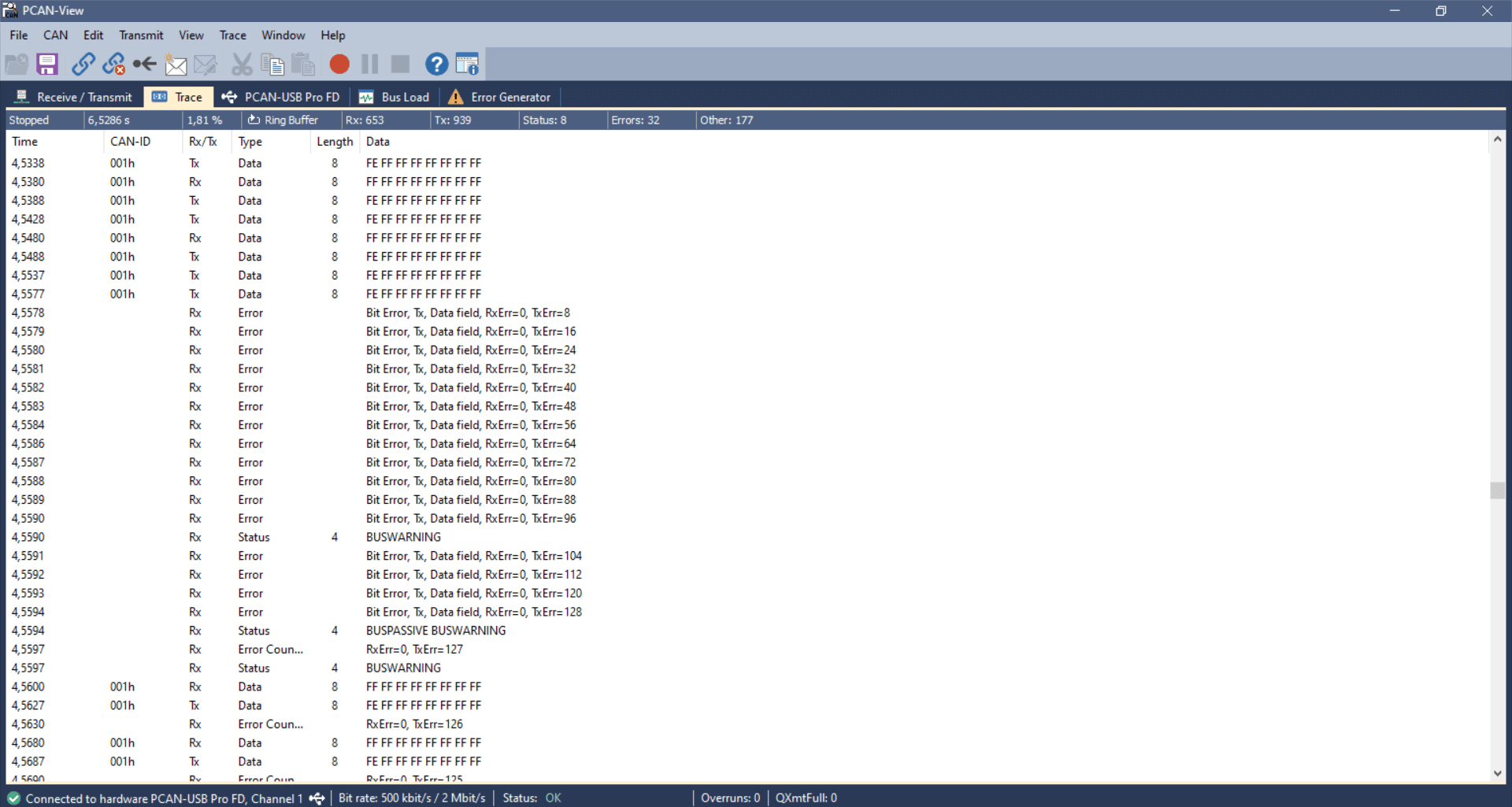
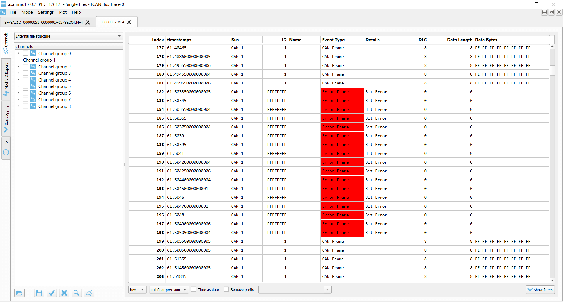
Test #5: CAN frame collisions (no retransmission)
When setting up a CAN bus, it is key to avoid overlapping CAN IDs. Failing to do so can result in frame collisions as two CAN nodes may both believe they've won the arbitration - and hence start transmitting their frames at the same time.
To simulate this, we use the same setup as in test #4. In addition, we connect a PCAN-USB device as a secondary transmitter.
The CANedge3 transmitter is now configured to output a single CAN frame every 10 ms with CAN ID 1 and a payload of eight 0xFF bytes. Further, we configure the CANedge3 to disable retransmission of frames that were disrupted by errors. The PCAN-USB outputs an identical CAN frame every 2 ms with the 1st byte of the payload changed to 0xFE. The PCAN device has retransmissions enabled.
This setup quickly creates a frame collision, resulting in the CANedge and PCAN transmitters detecting a Bit Error. In response to this, both raise an Active Error Flag, which is detected as a Bit Stuffing Error by the CANedge receiver. The PCAN device immediately attempts a retransmission and succeeds, while the CANedge waits with further transmission until the next message is to be sent.
This type of error should of course never happen in e.g. a car, since the design and test processes will ensure that all CAN nodes communicate via globally unique CAN identifiers. However, this problem can easily occur if you install a 3rd party device (e.g. a sensor-to-CAN module) to inject data into an existing CAN bus. If you do not ensure the global uniqueness of the CAN IDs of external CAN nodes, you may cause frame collisions and hence errors on the CAN bus. This is particularly important if your external CAN node broadcasts data with high priority CAN IDs as you may then affect safety critical CAN nodes.
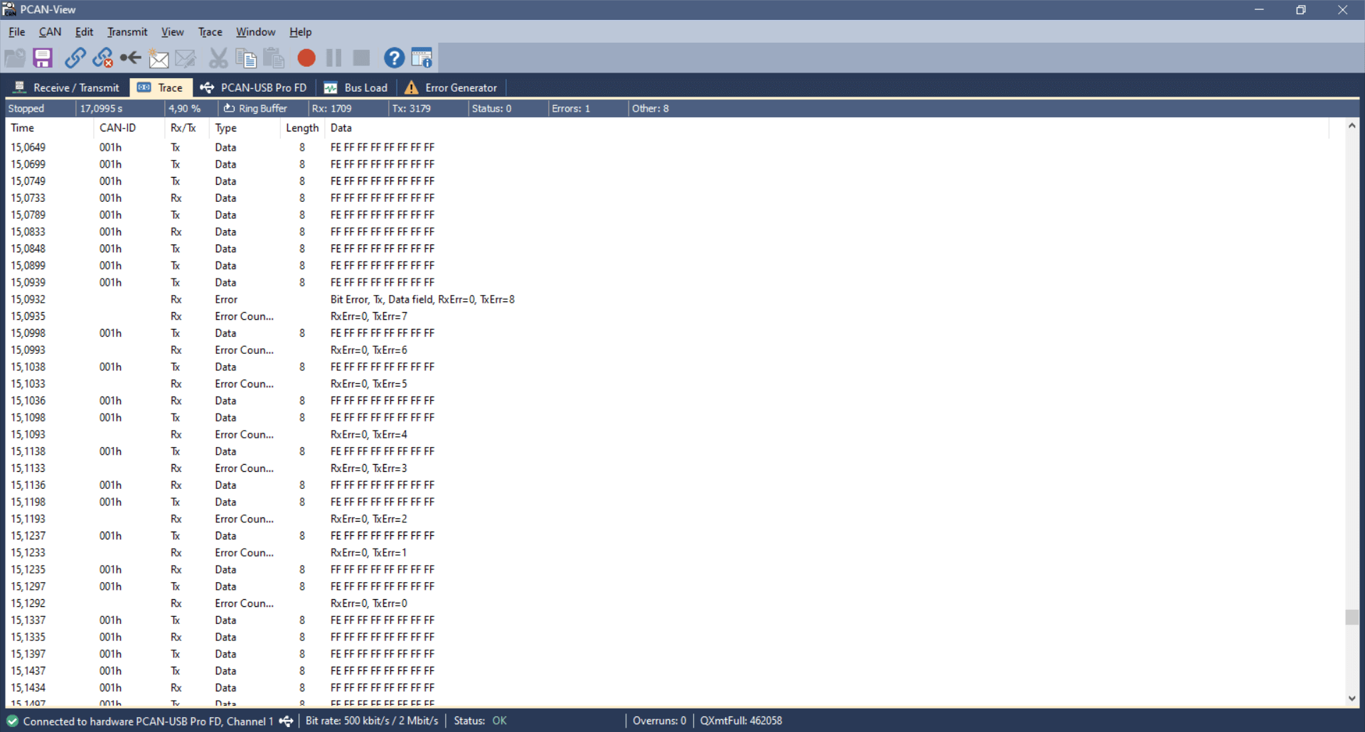 USB-to-CAN transmitter Bit Error
 CANedge transmitter Bit Error
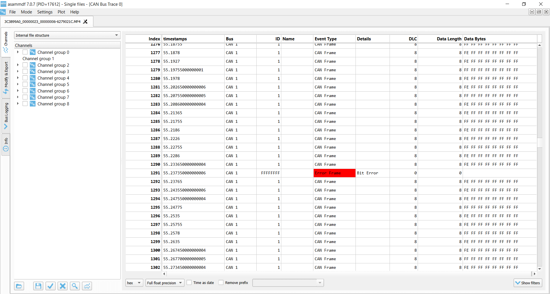
 CANedge receiver Bit Stuffing Error
Test #6: CAN frame collisions (incl. retransmission)
In this test, we use the same setup as before, but we now enable retransmissions on the CANedge3 transmitter.
In this case, the frame collision results in a sequence of frame collisions as both the CANedge3 and the PCAN-USB device attempt to re-transmit their disrupted messages.
Due to the resulting Bit Errors, both raise a total of 16 Active Error Flags, which are detected as Bit Stuffing Errors by the silent CANedge2 receiver. Both transmitters then enter Error Passive mode and stop raising Active Error Flags, meaning none of them can destroy CAN frames on the bus. As a result, one of the transmitters will succeed in transmitting a full message, thus ending the retransmission frenzy - and enabling both devices to resume transmission. However, this only lasts for a few seconds before another collision occurs.
The collision handling is a good example of how effective the CAN error handling is at 'shutting down' potentially problematic sequences and enabling CAN nodes to resume communication. If a frame collision occurs, it is likely that both CAN nodes will be set up to attempt retransmission, which would cause a jam if not for the error handling and confinement.
 USB-to-CAN transmitter Bit Errors x 16
 CANedge transmitter Bit Errors x 16
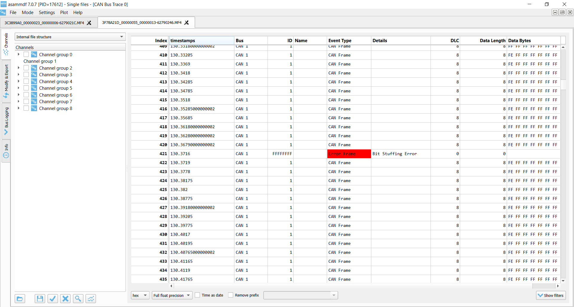
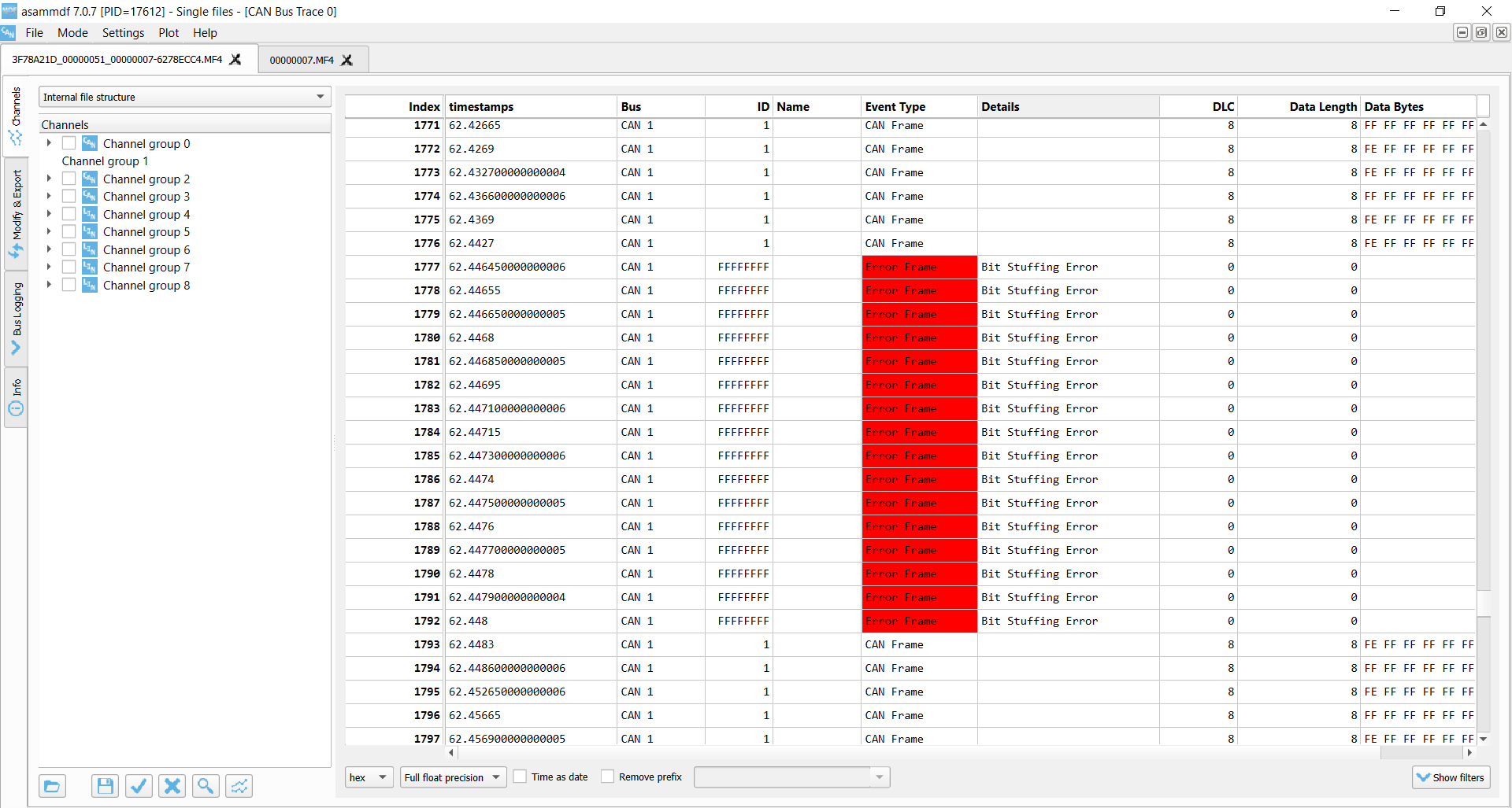 CANedge receiver Bit Stuffing Errors x 16
How to troubleshoot CAN errors
In practice, you will often encounter CAN bus errors during development and data logging. The degree of errors may vary: You may experience 100% CAN errors due to basic issues like improper termination of a test bench setup. Or, you may be trying to eliminate a frustrating 0.1% message loss from a critical telematics project by troubleshooting CAN bus bit timing issues.
Our overview lists the most common root causes for CAN bus errors and how to troubleshoot them.
We have put 'acknowledgement' as one of the top issues. This is because one of the most common reasons for CAN bus errors is when a user is trying to record data from a single CAN bus node using an external logger/interface. Here, the logger/interface may support a 'silent mode' in which the device does not acknowledge (ACK) CAN messages. As a result, since there is only one other CAN node on the test bench network, the communication will fail entirely. The solution is simply to disable silent mode in such test setups. The CANedge also supports a 'restricted' mode that blocks the device from transmitting CAN frames, but allows it to acknowledge CAN messages sent by other devices.
While silent mode should be disabled in setups like the above, it is recommended to enable it for field deployments when a CAN bus data logger is connected to an active CAN bus. This helps ensure that the external data logger does not interfere with the safety-critical CAN communication in any way. This is particularly important as an external device may otherwise introduce CAN bus errors into the system if e.g. the bit timing configuration is not fully matched vs. the CAN bus (see below).
As evident from the list, a common issue you may encounter relates to bit-rate issues. Of course, if you connect a CAN node that is configured to communicate at 500K to a CAN bus operating at 250K, the communication will fail completely.
However, a more subtle issue arises when you have small differences in the bit timing configuration of nodes. For example, you may connect two CAN nodes that both operate at 250K, yet still experience frame loss due to intermittent CAN bus errors (e.g. 0-1% loss). To resolve this, you may need to change the bit timing configuration of one of the CAN nodes (e.g. an external CAN bus data logger) to more closely resemble the settings of the other CAN node.
We provide a more detailed walkthrough of how this can be done in the CANedge documentation under 'Configuration/CAN/Physical'.

LIN bus errors
Similar to CAN bus errors, the LIN protocol also specifies a set of four error types, which we outline briefly below (see also our intro to LIN bus). The CANedge supports both CAN/LIN error frame logging.
As for the CAN CRC Error, this error type implies that a LIN node has calculated a different checksum vs. the one embedded in the LIN bus frame by the transmitter. If you're using the CANedge as a LIN Subscriber, this error may indicate that you've configured the device 'frame table' with incorrect identifiers for some of the LIN frames on the bus.
This can in turn be used to 'reverse engineer' the correct lengths and IDs of proprietary LIN frames via a step-by-step procedure. See the CANedge Docs for details.
These occur if a specific part of the LIN message does not match the expected value, or if there is a mismatch between what is transmitted vs. read on the LIN bus.
This error indicates an invalid synchronization field in the start of the LIN frame. It can also indicate a large deviation between the configured bit rate for a LIN node vs. the bit rate detected from the synchronization field.
Transmission errors can occur for LIN identifiers registered as SUBSCRIBER messages. If there are no nodes responding to a SUBSCRIBER message, a transmission error is logged.
Example use cases for CAN error frame logging
CAN bus diagnostics in OEM prototype vehicles
An automotive OEM may have the need to record CAN error frames in the field during late stage prototype testing. By deploying a CANedge, the OEM engineering team will both be able to troubleshoot issues based on the actual CAN signals (speed, RPM, temperatures) - as well as issues related with the lower layer CAN communication in their prototype systems. This is particularly vital if the issues of interest are intermittent and e.g. only happen once or twice per month. In such scenarios, CAN bus interfaces are not well suited - and it becomes increasingly relevant to have a cost-effective device to enable scalable deployments for faster troubleshooting.


Remotely troubleshooting CAN errors in machinery
An OEM or aftermarket user may need to capture rare CAN error events in their machines. To do so, they deploy a CANedge2 to record the CAN data and related error frames - and automatically upload the data via WiFi to their own cloud server. Here, errors are automatically identified and an alert is sent to the engineering team to immediately allow for diagnosing and resolving the issue. For 3G/4G transfer, a CANedge3 can alternatively be used.
Real-time CAN error frame analysis via USB
An OEM engineer may need to inspect CAN error frames live while bringing up a new ECU on the bench or reproducing an intermittent fault on a prototype vehicle. By connecting a CANsub.2/CANsub.4 to the CAN bus and to a laptop via USB, the engineer gets an instant browser-based view of every CAN frame and error frame via webCAN - with zero software installation. This makes it easy to correlate error bursts with specific stimuli (cable disconnects, termination changes, ECU resets) and iterate quickly on the fix. For deeper offline analysis, the same error frames can be streamed into SavvyCAN or processed via the Python API.

FAQ
No, error frame logging is a highly specific functionality - and only relevant if you know that you need to record this information. Typically, it's mainly of value during diagnostics by OEM engineers - and less so for aftermarket users. In addition, if systematic errors occur they can quickly bloat the log file size.
With the CANedge2 you can of course enable/disable error frame logging over-the-air.
Yes, the CANedge is able to record all CAN/LIN error types. It does, however, not currently record its own error counter status as this is deemed less relevant from a logging perspective.
The CANedge is only able to raise error flags onto the CAN bus if it is configured in its 'normal' mode, in which it is also able to transmit messages. If in 'restricted' mode it can listen to CAN frames and acknowledge CAN frames - but not raise Active Error Flags onto the bus. In 'monitoring' mode (aka 'silent mode') it can listen to the CAN bus traffic, but not acknowledge messages nor raise Active Error Flags.
The CANedge will always record internal CAN/LIN error frames.
If a CAN frame is erroneous, resulting in an error frame, the CANedge generally only records the error type - without any data related to the erroneous frame (beyond the timestamp). One exception to this rule is for acknowledgement errors, where the CANedge will still record unacknowledged CAN frames (incl. from retransmission attempts).
Some researchers have pointed out the risk that 'bad actors' could utilize the CAN bus error handling functionality to enforce remote 'bus off' events for safety-critical ECUs. This is a good example of why CAN bus data loggers & interfaces like the CANedge2 with remote over-the-air data transfer and updates need to be highly secure (see also our intro to CAN cybersecurity). For a nice overview of a remote bus off attack, see this intro by Adrian Colyer.
For more intros, see our guides section - or download the 'Ultimate Guide' PDF.
Need to log CAN bus data & errors?
Get your CAN logger today!


