J1939 Explained - A Simple Intro [2026]
Need a simple intro to SAE J1939?
In this guide we introduce the J1939 protocol basics incl. PGNs and SPNs, key characteristics, request messages and the transport protocol.
Note: This is a practical intro so you will also learn how to decode raw J1939 data with real-life example data.
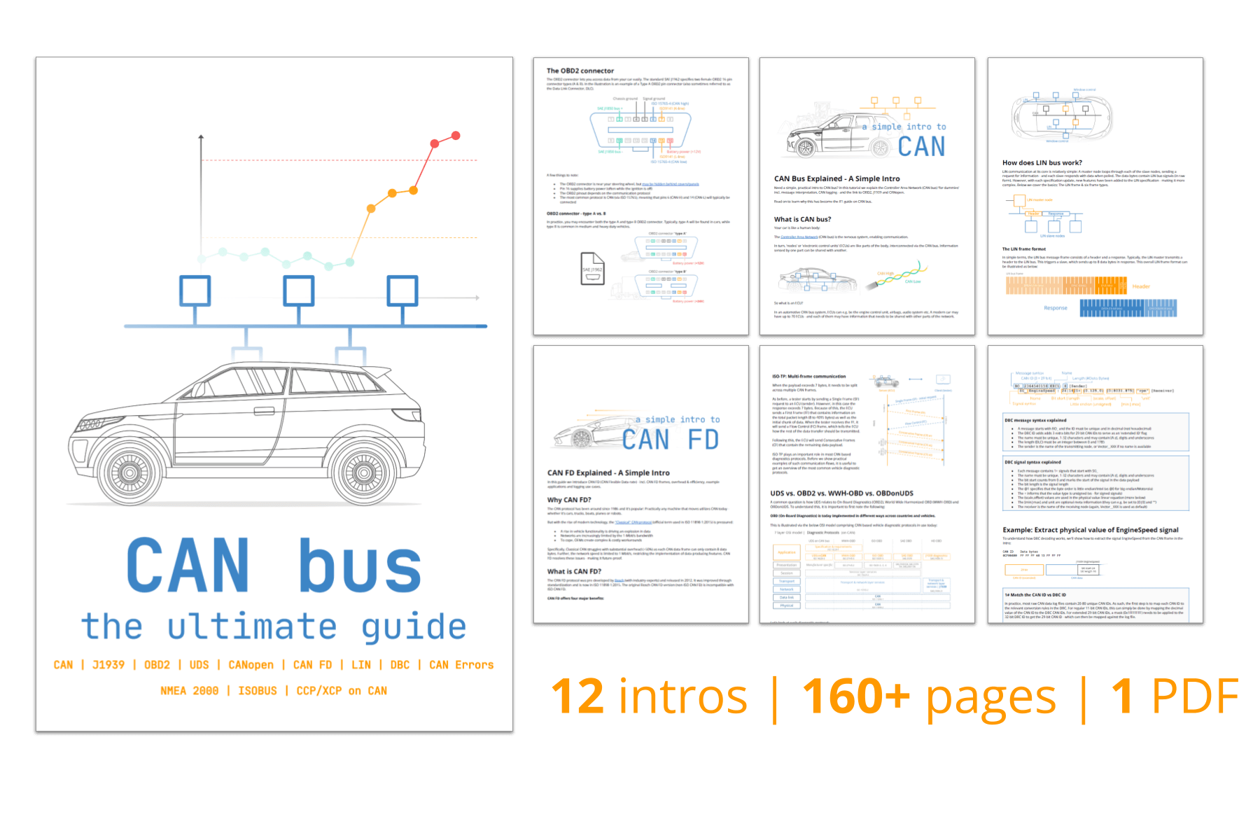
Learn below why this has become the #1 introduction to J1939.
You can also watch our J1939 intro above - or get the PDF.
In this article

What is J1939?
SAE J1939 is a set of standards that define how ECUs communicate via CAN bus in heavy-duty vehicles.
As explained in our CAN bus intro, most vehicles today use the Controller Area Network (CAN) for ECU communication. However, CAN bus only provides a "basis" for communication - not a "language" for conversation.
In most heavy-duty vehicles, this language is the SAE J1939 standard defined by SAE International.
In more technical terms, J1939 provides a higher layer protocol based on CAN (more on this later).
What does that mean, though?


One standard across heavy-duty vehicles
In simple terms, J1939 offers a standardized method for communication across ECUs, or in other words:
J1939 provides a common language across manufacturers.
In contrast, e.g. cars use proprietary OEM specific protocols.
The J1939 standardization is a key enabler to data logging use cases across heavy-duty vehicles - more on this below.
Heavy-duty vehicles (e.g. trucks and buses) is one of the most well-known applications. However, several other key industries leverage SAE J1939 today either directly or via derived standards (e.g. ISO 11783, MilCAN, NMEA 2000, FMS):
- Foresting machines (e.g. delimbers, forwarders, skidders)
- Mining vehicles (e.g. bulldozers, draglines, excavators, …)
- Military vehicles (e.g. tanks, transport vehicles, …)
- Agriculture (e.g. tractors, harvesters, …)
- Construction (e.g. mobile hydraulics, cranes, …)
- Fire & Rescue (e.g. ambulances, fire trucks, …)
- Other (e.g. ships, pumping, e-buses, power generation, ...)
SAE International (previously known as Society of Automotive Engineers) is a global standards organization based in USA. The organization plays a critical role in the development and maintenance of the J1939 standard. For example, the organization ensures the protocol is updated in response to developments like vehicle electrification and the rise of CAN FD.
4 key characteristics of J1939
The J1939 protocol has a set of defining characteristics outlined below:

250K baud rate &
29-bit extended ID
The J1939 baud rate is typically 250K (though recently with support for 500K) - and the identifier is extended 29-bit (CAN 2.0B)

Broadcast + on-request data
Most J1939 messages are broadcast on the CAN-bus, though some data is only available by requesting the data via the CAN bus

PGN identifiers & SPN parameters
J1939 messages are identified by 18-bit Parameter Group Numbers (PGN), while J1939 signals are called Suspect Parameter Numbers (SPN)

Intel byte order & multi-packets
Multibyte signals are sent least significant byte first (Intel byte order). PGNs with up to 1785 bytes are supported via J1939 transport protocol
Below are a set of additional characteristics of the J1939 protocol:
- Reserved: J1939 includes a large range of standard PGNs, though PGNs 00FF00 through 00FFFF are reserved for proprietary use
- Special values: A data byte of 0xFF (255) reflects N/A data, while 0xFE (254) reflects an error
- J1939 address claim: The SAE J1939 standard defines a procedure for assigning source addresses to J1939 ECUs after network initialization via an 8-bit address in a dynamic way
J1939 history
- 1985: SAE initiated development of the J1939 protocol
- 1994: First docs were released (J1939-11, J1939-21, J1939-31)
- 2000: The initial top level document was published
- 2000: CAN formally included as part of J1939 standard
- 2001: J1939 starts replacing former standards SAE J1708/J1587
- 2013: J1939 Digital Annex released, digitizing PGN/SPN data
- 2020-21: J1939-17 and J1939-22 released (J1939 on CAN FD)


J1939 future
We see a number of trends affecting the protocol:
- Bandwidth challenge: The need for more bandwidth may drive a transition towards J1939-22 (J1939 on CAN FD), increasing use of separate J1939 networks per vehicle and/or a potential transition towards Automotive Ethernet
- Right to Repair: The 'Right to Repair' movement is particularly relevant in expensive heavy-duty vehicles, incl. e.g. famously John Deere equipment and military vehicles. At the same time, OEMs are commercially motivated to increasingly offer closed J1939 telematics systems, which may drive a push towards the use of increasingly proprietary PGN/SPN encoding
- J1939 EVs: The increase in electric heavy-duty vehicles poses a risk to the J1939 standardization and thus e.g. mixed fleet telematics. This is both due to the absence of legal requirements for emissions measurements and the fact that OEM EV development may sometimes precede the introdution of new standardized J1939 PGN/SPN encoding
J1939 standards (higher-layer protocol)
J1939 is based on CAN, which specifies the physical layer (ISO 11898-2) and data link layer (ISO 11898-1) of the OSI model.
Here, CAN is a 'lower-layer protocol' that specifies means of communication like wires and CAN frames - but not a lot more.
J1939 is a 'higher-layer protocol' that adds a specific language to enable more advanced communication. Other CAN based protocols exist like OBD2, UDS and CANopen.
To better understand J1939, we will explore some of the sub standards (or chapters) in the sections below.


The J1939 connector [J1939-13]
The J1939-13 standard specifies the 'off-board diagnostic connector' - also known as the J1939 connector or 9-pin deutsch connector. This is a standardized method for interfacing with the J1939 network of most heavy duty vehicles - see the illustration for the J1939 connector pinout.
As evident, the J1939 deutsch connector provides access to the J1939 network through pins C (CAN high) and D (CAN low). This makes it easy to interface with the J1939 network across most heavy duty vehicles.
In some cases, however, you may also be able to access a secondary J1939 network through pins F and G or pins H and J (with H being CAN H and J being CAN L).
Many of today's heavy duty vehicles have 2 or more parallel CAN bus networks and in some cases at least two of these will be available through the same J1939 connector. This also means that you will not necessarily have gained access to all the available J1939 data if you've only attempted to interface through the 'standard' pins C and D.
While the J1939 deutsch connector is the most common way to interface with the J1939 network of heavy duty vehicles, other connectors of course exist. Below are some examples:
- J1939 Backbone Connector: This 3-pin deutsch connector provides pins for CAN H/L a CAN shield (no power/ground)
- CAT connector: The Caterpillar industrial connector is a grey 9-pin deutsch connector. However, the pin-out differs from the J1939 connector (A: Power, B: Ground, F: CAN L, G: CAN H) and the connector physically blocks access from standard type 1 and 2 J1939 connectors
- OBD2 type B connector: The type B OBD2 connector (SAE J1962) in heavy duty vehicles sometimes provide direct access to the J1939 network through pins 6 and 14
- Volvo 2013 OBD2 connector: This variant matches the type B OBD2 connector, but also adds access to the J1939 high via pin 3 and J1939 low via pin 11
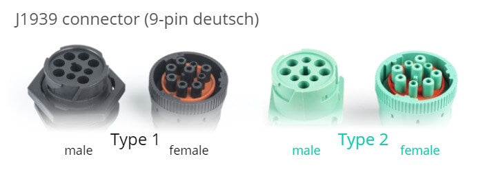
Black type 1 vs green type 2
Note that the J1939 deutsch connector comes in two variants: The original black connector (type 1) and the newer green connector (type 2), which started getting rolled out in 2013-14. Green type 2 J1939 adapter cables can be used on both black and green connectors as they are backwards compatible.
J1939 type 2 female connectors are physically backwards compatible, while type 1 female connectors only fit type 1 male sockets. The type 2 connector was designed for the SAE J1939-14 standard, which adds support for 500K bit rates. The purpose of "blocking" type 1 connectors is to ensure that older hardware (presumably using 250K bit rates) is not connected to type 2 500K bit rate J1939 networks. Specifically, the physical block is through a smaller hole for pin F in the type 2 male connectors.
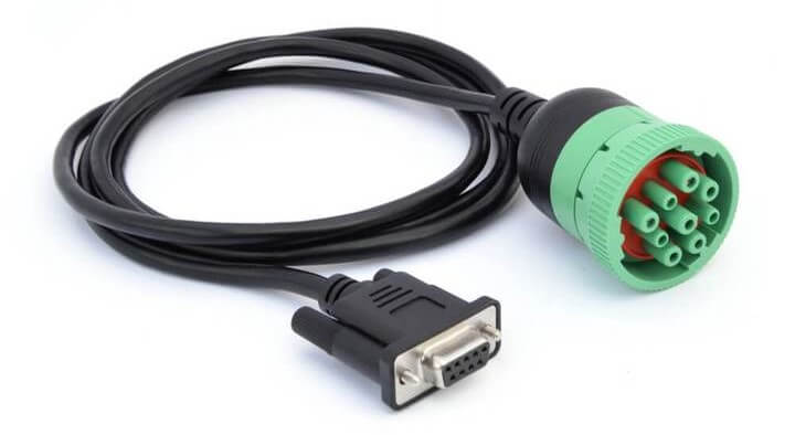
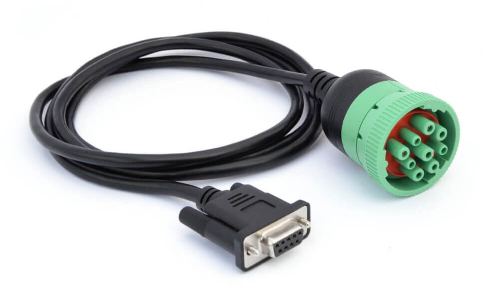
Below is an example of a DB9-J1939 adapter cable (type 2):
The J1939 PGN and SPN [J1939-21/71]
In the following section we explain the J1939 PGNs and SPNs.
Parameter Group Number (PGN)
The J1939 PGN comprises an 18-bit subset of the 29-bit extended CAN ID. The PGN serves as the unique frame identifier within the J1939 standard - meaning that the rules for decoding raw J1939 data are specified at PGN level, rather than 29-bit ID level.
As a result, multiple CAN messages with unique CAN IDs can map to the same PGN - and be interpreted identically.


Detailed breakdown of the J1939 PGN
Let's look at the CAN ID to PGN transition in detail.
Specifically, the 29 bit CAN ID comprises the Priority (3 bits), the J1939 PGN (18 bits) and the Source Address (8 bits). In turn, the PGN can be split into the Reserved Bit (1 bit), Data Page (1 bit), PDU format (8 bit) and PDU Specific (8 bit). PDU refers to Protocol Data Unit.
The detailed PGN illustration also includes example values for each field in binary, decimal and hexadecimal form.
Tip: CAN ID to J1939 PGN converter
Our online J1939 PGN converter lets you convert 29-bit CAN IDs to J1939 PGNs - and vice versa. The tool also lets you check if the J1939 PGN is included in our J1939 DBC file.
J1939 PGN converter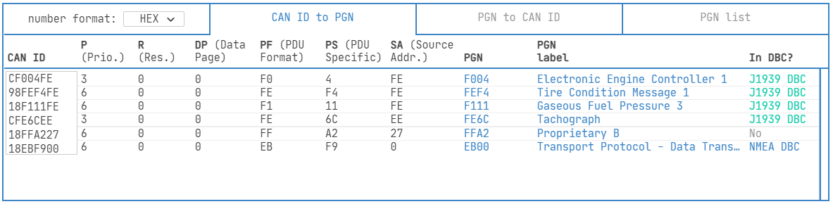
A common confusion on J1939 PGNs relates to PDU1 vs. PDU2.
Most users may be more familiar with PDU2 PGNs because these make up ~95% of the PGNs in the J1939 Digital Annex. PDU2 messages are 'broadcast', meaning they are transmitted with no specific destination - and all CAN nodes decide whether to use or ignore the data. PDU1 messages are 'addressable' and the CAN ID contains a 'destination address' that allows for targeting a specific node on the bus.
To see this in practice, let us take outset in two PGNs: 61444 (EEC1) and 11264 (HVESP3C1). In the picture below, we have entered three separate 29-bit CAN IDs for both of these PGNS in our J1939 PGN converter:
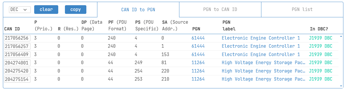
Notice how EEC1 is PDU2 as the PDU Format is 240, while HVESP3C1 is PDU1 as the PDU Format is 44 (and hence below 240). For EEC1, the PDU Specific (PS) field is 4 throughout, which will be the case for any 29-bit CAN ID that maps to the EEC1 PGN. Here, the value 4 reflects the Group Extension. In contrast, the PDU Specific (PS) field varies across the three 29-bit CAN IDs that map to the HVESP3C1 PGN. The different PS values reflect different destination addresses.
Distinguishing between PDU1 and PDU2 is e.g. relevant when using J1939 PGN masks in the configuration of CANedge ID filters. Here, a mask of 3FFFF00 can be used for PDU2, while a mask of 3FF0000 must be used for PDU1.

Suspect Parameter Number (SPN)
The J1939 SPN serves as the identifier for the CAN signals (parameters) contained in the data payload. SPNs are grouped by PGNs and can be described in terms of their bit start position, bit length, scale, offset and unit - information required to extract and scale the SPN data to physical values.
Examples of SPNs include Engine Speed, Wheel Based Vehicle Speed, Fuel Level 1 and Engine Oil Temperature 2.
J1939 Digital Annex & J1939 DBC file
In 2013, the J1939 Digital Annex (DA) was introduced by SAE. This is an Excel file that contains all technical details on standard J1939 PGNs and SPNs, previously published in J1939-71.
Importantly, the J1939 DA only includes standardized PGNs/SPNs - not OEM specific proprietary PGNs/SPNs.
At CSS Electronics, we collaborate with SAE to transform the J1939 DA into a J1939 DBC file with 1,800+ PGNs and 10,000+ SPNs. This conversion is done quarterly with each new J1939 DA revision. The J1939 DBC file can be used in CAN software/API tools to enable easy decoding of raw J1939 data.
j1939 dbc intro
How to decode raw J1939 data
As hinted above, practical decoding of J1939 data is done via CAN software/API tools and a J1939 DBC file. However, it is useful to understand what is happening under-the-hood.
Assume you have recorded a raw J1939 frame as below:
| CAN ID | Data bytes |
| 0x0CF00401 | 0xFF FF FF 68 13 FF FF FF |
First, you need to determine the J1939 PGN, e.g. via our PGN converter. The 29-bit CAN ID 0x0CF00401 translates to J1939 PGN 0xF004 (61444) aka EEC1 (Electronic Engine Controller 1).
From the J1939-71 DA, we find that the PGN EEC1 contains 8 SPNs - including Engine Speed.


Next, we will decode the value of Engine Speed. In the J1939 DA we can look up the decoding rules and follow the below steps:
- Extract raw bits: The raw payload is in bytes 4 to 5, i.e. 0x6813
- Use Intel: Next, reverse the byte order to get 0x1368
- Convert to decimal: The raw payload in decimal form is 4968
- Scale/offset: Multiply by 0.125 and offset by 0 to get 621 RPM
J1939 signal ranges
As per J1939-71, some signal values have special interpretations. If an ECU has a sensor error or lacks certain functionality entirely, the 'error range' or 'not available range' can be used to communicate this. You can see the practical use of 'not available' values in the below raw J1939 data example.
Note that the J1939 DA specifies an 'operational range' for many signals, which is more restricted than the 'valid range'. In the J1939 DBC file, we include min/max values for all signals, leveraging the operational range when available - and otherwise the 'valid range'.
For 2-bit discrete parameter signals, J1939-71 states that the value 2 reflects an error and the value 3 reflects not available. However, in our experience this seems to contradict the J1939 Digital Annex SPN descriptions, where several 2-bit signals utilize the full set of 4 potential values to communicate valid data. For this reason, we do not include the 2-bit signal length in the table, as we recommend instead to consult the J1939 Digital Annex itself.
 The ranges show extracted data byte values after reversing the byte
order
The ranges show extracted data byte values after reversing the byte
order
Example: J1939 truck data - raw vs. decoded
Below we illustrate raw vs. decoded J1939 data through an example.
The two pictures show a log file recorded using a CANedge2 from a truck, visualized via the free asammdf GUI:
Raw J1939 data
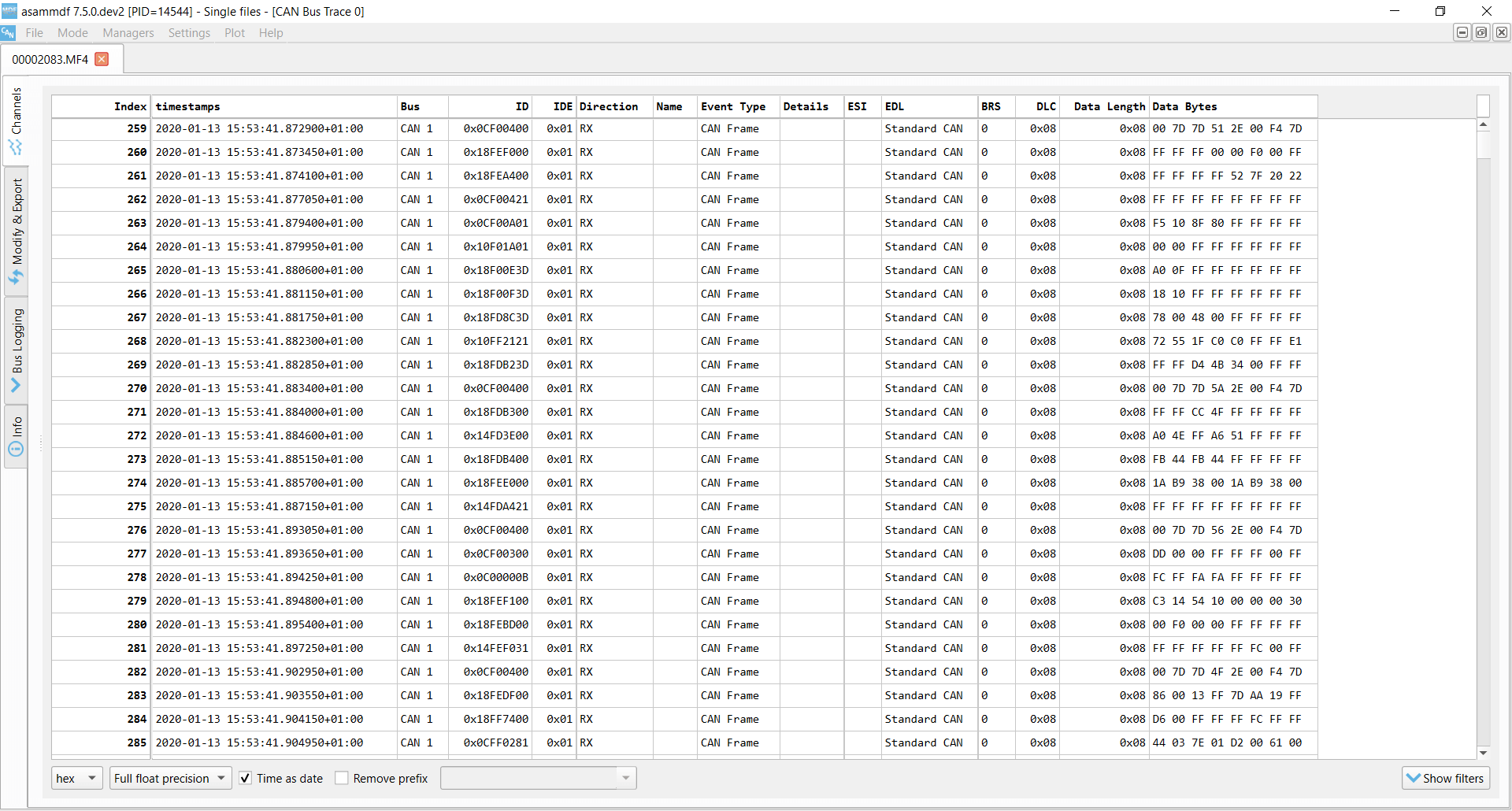
The raw J1939 data is comprised of timestamped 29-bit CAN IDs and 8-byte data payloads. This data can be filtered and searched through, but cannot e.g. be plotted as time series
Decoded J1939 data
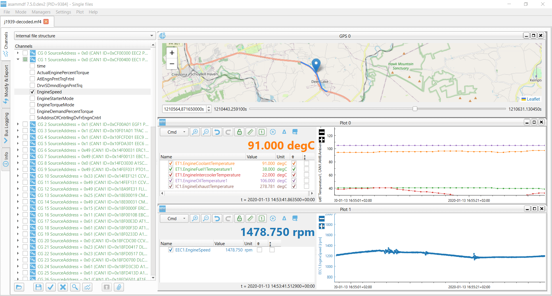
By decoding the raw J1939 data with a J1939 DBC file, we match 85 of 142 CAN IDs (the rest is proprietary). The decoded file contains J1939 SPNs grouped by PGNs - ready for analysis
Want to try this yourself? Download asammdf, our J1939 sample data and J1939 DBC demo:
try it nowCANedge: J1939 data logger
The CANedge lets you easily record J1939 data to an 8-32 GB SD card - or use the CANedge2 / CANedge3 to also offload it via WiFi/LTE. Simply connect it to e.g. a truck to start logging - and decode the data via free software/APIs and our J1939 DBC.
j1939 logger intro CANedgeCANsub: J1939-USB interface
The CANsub.2/CANsub.4 lets you stream 2-4 x J1939 channels in real-time via USB or Ethernet - viewing live frames and DBC decoded J1939 signals directly in your browser via webCAN. The software supports a PGN view, J1939 DBC files and J1939 TP.
Buy now webCAN software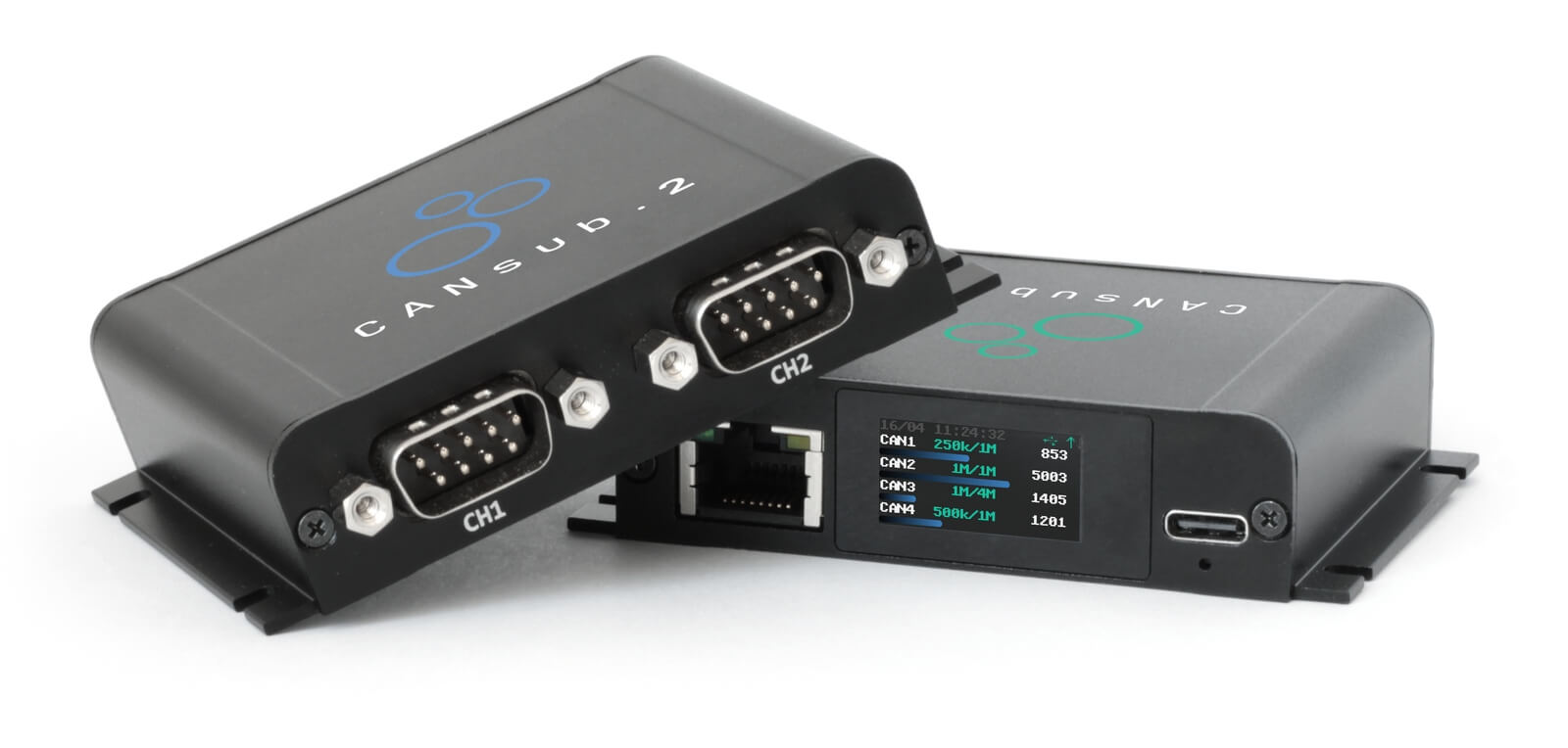
Request message [J1939-21]
Most J1939 messages are transmitted on the CAN bus at a fixed periodic rate, but some are only transmitted 'on-request' (e.g. when polled by a diagnostic tool or J1939 data logger).
A common example includes J1939 diagnostic messages like the DM2, which contains diagnostic trouble codes (DTCs). See also our J1939-73 DBC file.
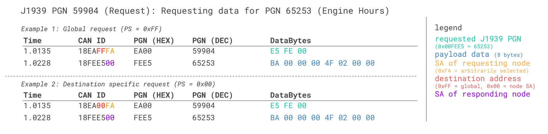
To send a J1939 request via the CAN bus, a special 'request message' is used (PGN 59904), which is the only J1939 message with just 3 data bytes. The data bytes contain the requested PGN in Intel byte order.
To show how this works, let us consider a real-life example. Here, an engineer is using the CANedge to request data on the PGN HOURS (0xFEE5 i.e. 65253), which includes the SPN 'Engine Total Hours of Operation' (often used in e.g. telematics).
To send the request, the engineer configures the CANedge to transmit a CAN frame with a payload of 0xE5FE00 (the HOURS PGN in Intel byte order).


For the 29-bit CAN ID we illustrate two cases:
- Example 1: Here the destination address is 0xFF (a 'global request'), forcing all ECUs to respond if they have data
- Example 2: Here the destination address is 0x00 (a 'specific request'), ensuring only the ECU with SA 0x00 responds
In practical applications, you will typically not know the source address of the ECU you're looking to request data from. For example, if you are looking to extract HOURS across 5 different heavy-duty trucks, the simplest solution is to simply use the 0xFF global request - at least during initial exploration.
Many practical J1939 buses use fixed source addresses, meaning that you can use a two-step process: First you identify the source address of the responding ECU(s) via the global request - and once the address is known, you switch to the specific request method. This can be preferable, e.g. if multiple ECUs respond with identical data when you perform the global request. Here, using specific requests helps reduce busload and log file size.
Note also that we use a source address of 0xFA for the CANedge in the trace example. This is somewhat arbitrary: Industry conventions typically recommend that 3rd party tools use a source address in the 'upper range' (e.g. 0xFA-0xFF), though the J1939 standard does not dictate a specific address. The source address used in the request ID will not affect the results, but it is considered good practice to use a unique source address if possible.
Sending request messages is typically key to requesting J1939 codes and thus J1939 diagnostics. One challenge, however, is that J1939 loggers are often required to have a contactless connection to the J1939 data link, meaning that they're unable to interact with the CAN bus and transmit J1939 request frames. The restriction is often related to warranty compliance as some vehicle manufacturers do not allow direct access by 3rd party devices via the J1939 connector.
In some cases, it is required that the J1939 analyzer is "physically" contactless, e.g. via a contactless CAN reader. In other cases, it is sufficient that the J1939 logger operates in "configurable" silent mode. The latter makes it easier to perform ad hoc requests for J1939 fault codes, either via a manual configuration update or via an over-the-air update for the CANedge2.
 A J1939-DB9 allows read/write access to the CAN
J1939 transport protocol (TP) [J1939-21]
Some message payloads exceed 8 bytes - for example ECU software updates, vehicle configurations or diagnostic trouble codes (DM1). To communicate such payloads it is necessary to split the data across multiple CAN frames. The receiving node must then subsequently reassemble the individual data packets.
J1939 specifies how this can be achieved through two alternative transport protocols:
Peer-to-Peer (RTS/CTS)

The transmitting node initiates a connection via a Request To Send (RTS) message. Subsequent communication is controlled by the receiver through Clear To Send (CTS) messages, ending with a End of Message Acknowledge (EoMA) message.
Broadcast (BAM)

The transmitting node initiates the communication with a Broadcast Announce Message (BAM, PGN 0xEC00 i.e. 60416) followed by a number of Data Transfer (DT, PGN 0xEB00 i.e. 60160) messages. The receiving node does not exert any control.
Example: J1939 BAM transport protocol incl. reassembly
The J1939 transport protocol uses two PGNs:
- TP.CM: TP - Connection Management (0xEC00 i.e. 60416)
- TP.DT: TP - Data Transfer (0xEB00 i.e. 60160)
The TP.CM payload contains a control byte that differs depending on the type of message (it is e.g. 0x20 for the BAM message). The payload also contains the number of data bytes and packets to be sent and the PGN of the multi-packet message (Intel byte order)
In the BAM protocol, the TP.CM message is followed by up to 255 packets of data in TP.DT messages. The TP.DT message uses the 1st byte as a sequence counter (1 to 255), while the remaining 7 bytes contain the segmented data payload. As a result, a single J1939 TP sequence can carry up to 7 x 255 = 1785 data bytes.


Below we show a real-life trace of a J1939 transport protocol (BAM) sequence with data from the PGN EC1:
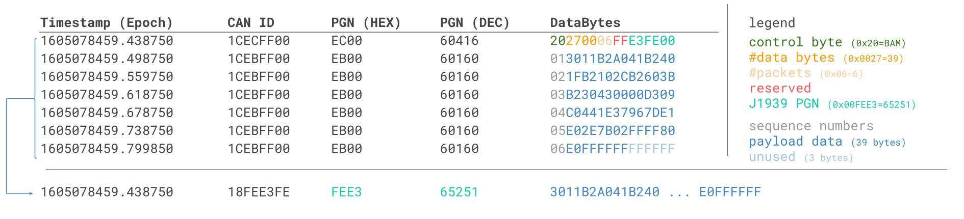
To interpret the EC1 data, the BAM protocol multi-packet data payload has to be reassembled:
- Identify the BAM frame (PGN 60416, control byte 0x20), indicating a new sequence being initiated
- Extract the PGN from the last 3 bytes of the BAM payload
- Convert the J1939 PGN into a 29-bit ID and use it as identifier of the reassembled frame
- Construct the reassembled data payload by concatenating the last 7 bytes of the data transfer frames
The reassembly and subsequent DBC decoding can be done via e.g. the CANedge software/API tools.
Above, the last 3 bytes of the BAM equal E3FE00. When reordered, these equal the PGN FEE3 aka Engine Configuration 1 (EC1). Further, the payload is found by combining the the first 39 bytes across the 6 data transfer packets/frames.
Note: The last 3 data payload bytes in this practical example happen to be FF, yet we still include these in the payload as the BAM message specifies the data length to be 39. The final 3 FF bytes in the 6th packet are unused/invalid.
With the method explained above, we have reassembled a J1939 data frame with a data length exceeding 8 bytes. This frame can be decoded using a J1939 DBC file, just like a regular 8-byte J1939 data frame. For the PGN EC1, the J1939 DBC specifies a data length of 40 with signals defined for the full payload.
As such, once the J1939 software/API has reconstructed the multi-frame response into a single J1939 frame, the DBC decoding can be done as usual. One minor tweak is that most J1939 DBC files expects that the raw log file of J1939 data will contain 29-bit CAN IDs (not 18-bit J1939 PGNs). As such, the software/API reassembly process typically also has to transform the PGN into a 29-bit ID. For inspiration, see our J1939 PGN converter which also offers this 'reverse' PGN to CAN ID conversion.
The CANedge lets you request and record J1939 transport protocol data. To decode the TP data, you can either convert the raw log files to another format (like Vector ASC), or you can use our Python API or MF4 decoders.
You can also use the CANsub CAN-USB/Ethernet interface to stream raw J1939 data in real-time. The free webCAN software lets you optionally enable J1939 TP to see the raw assembled frames in real-time - and DBC decode them.
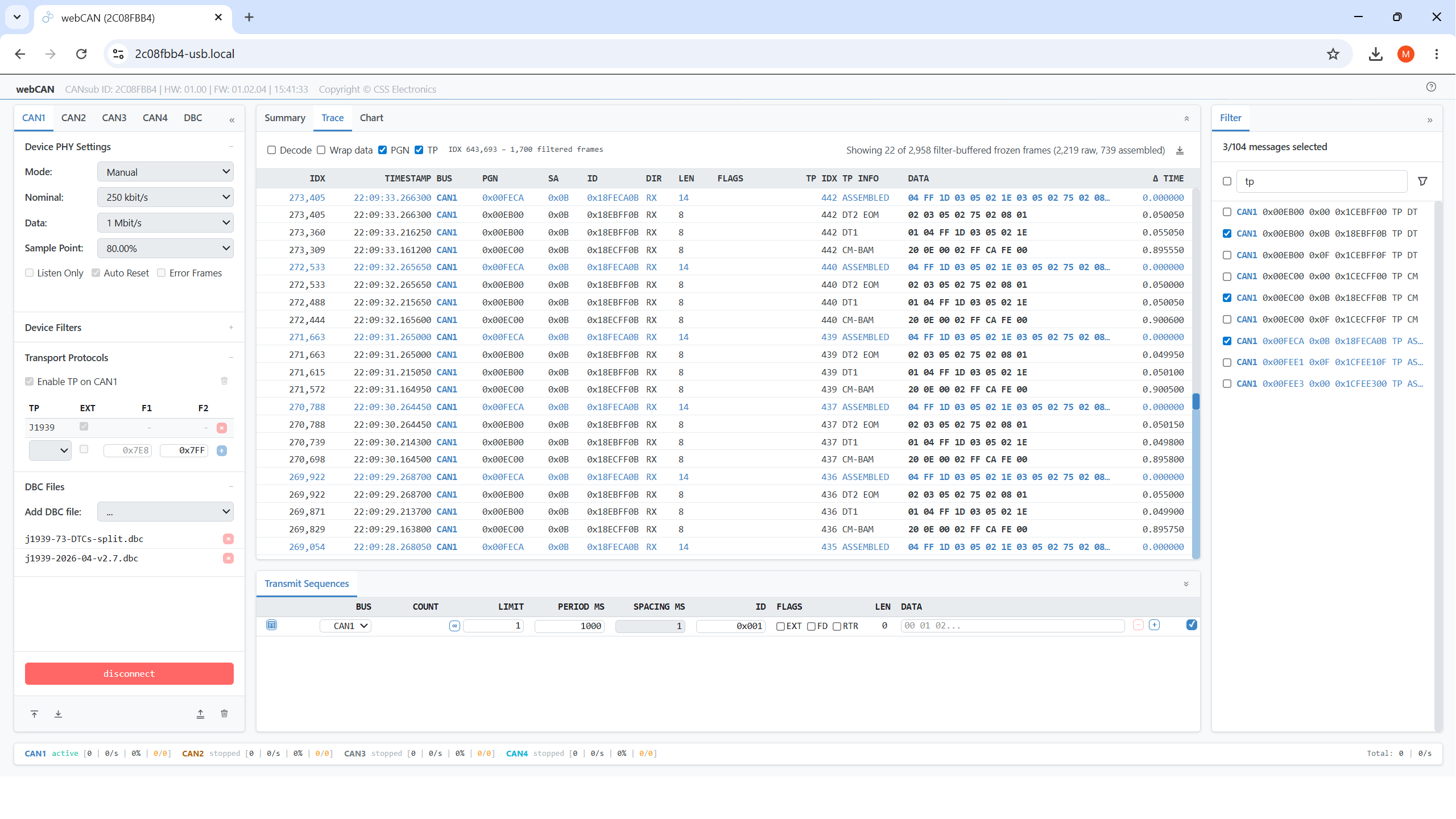
Example: J1939 TP assembly in webCAN
The CANsub.2/CANsub.4 stream 2-4 x J1939 channels in real-time via USB or Ethernet directly into webCAN in your browser.
With J1939 TP enabled, webCAN automatically tags BAM and CM/CTS sessions and assembles the TP frames from successful sequences. With a J1939 DBC loaded, the assembled frames are DBC decoded on the fly into named SPN signals with engineering units, ready for e.g. live plot visualization.
J1939 data logging - example use cases
There are several common use cases for recording J1939 data:

Heavy duty fleet telematics
J1939 data from trucks, buses, tractors etc. can be used in fleet management to reduce costs or improve safety
j1939 telematics
Live stream diagnostics
By streaming decoded J1939 data to a PC, technicians can perform real-time J1939 diagnostics on vehicles
j1939 streaming
Vehicle predictive maintenance
Vehicles can be monitored via WiFi CAN loggers in the cloud to predict breakdowns based on the J1939 data
predictive maintenance
Heavy-duty vehicle blackbox
A CAN logger can serve as a 'blackbox' for heavy-duty vehicles for e.g. disputes, J1939 diagnostics or events (EDR)
can bus blackboxDo you have a J1939 data logging/streaming use case? Reach out for free sparring!
Contact usFor more intros, see our guides section - or download the 'Ultimate Guide' PDF.
Need to log/stream J1939 data?
Get your CAN logger/interface today!


