


 PLUG & PLAY
Standalone - no PC required. Integrate with any CAN bus to add input sensor data. DBC included
 COMPACT
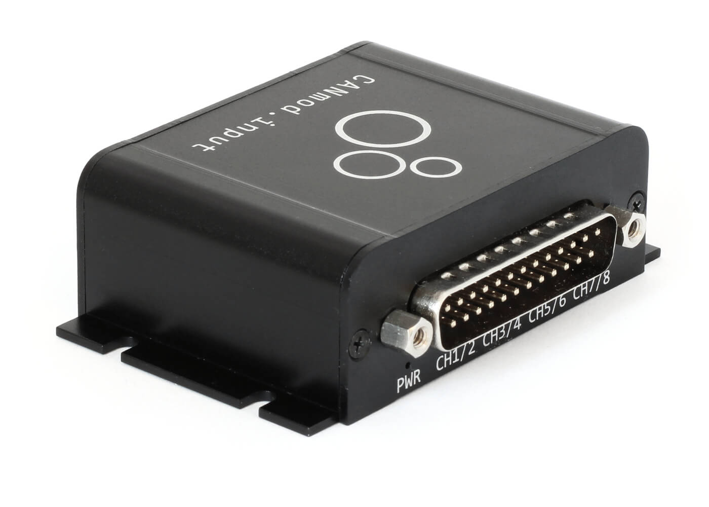
7 x 2 x 5 CM. 70G. 8 LEDs. 5-26 V DC via DB9. 3.3V excitation signals. USB for config/FW/stream
 8 X ANALOG
8 analog input channels (1 kHz, 10 bit). Configurable voltage ranges (0-0.625V to 0-10V)
 +DIGITAL
Digital input reading of each channel. 1 kHz. Configurable low/high/hysteresis
 +PULSE
Pulse input reading of each channel. 16 kHz. Frequency or counter mode (up to 32 bit)

Connect analog sensors
Sensors that produce analog outputs include force/pressure (load cells), current, distance (ultrasonic, laser, lidar, infrared), rotation (potentiometers), temperature, hall effect, magnometers, humidity, sound, atmospheric pressure, acceleration, gyroscopes - and many more.

Connect digital sensors
Sensors with digital outputs include hall effect switches, buttons (for e.g. registering events), reed switches (e.g. for door/valve/latch position registration), resistance-to-digital (RTD) sensors and more. Many sensors with analog outputs also produce optional digital outputs.

Connect pulse sensors (frequency, counter)
Sensors with pulse-oriented outputs include rotational speed sensors (e.g. hall effect frequency sensors), rotational position sensors, buttons & toggle switches (event counters), frequency meters and sensors producing e.g. Pulse Width Modulation (PWM) outputs.

Easily add analog/digital/pulse data to any CAN bus system
Add analog/digital/pulse data via 8 input channels to your CAN bus - e.g. for use by ECUs or CAN hardware.
- Powerful parallel sampling of analog/digital/pulse signals
- Configure input range for optimal resolution/amplification
- Configure digital high/low levels incl. optional hysteresis
- Dedicated excitation signal for powering input sensors (~3.3 V)
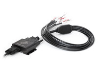
- Quickly connect sensors via optional DB25-input adapter cable
- Replace excitation signal with e.g. 12V/24V via DB25-DB25/DB9
- Optionally output signals via CAN FD for fewer frames
- Daisy-chain multiple modules for 16, 24, 32, ... channels
- Power device at 5-26 V DC via standard DB9 adapter cables
- Optionally record the data via any CAN interface/logger/...
- DBC file included for easy decoding to human-readable form


Example: Log/stream sensor data
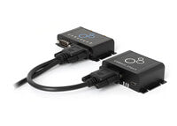
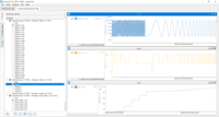
The CANmod.input is often used as an 'add-on' for the CANedge. This setup lets you record e.g. vehicle data via Channel 1 and analog/digital/pulse data via Channel 2. The data can be easily DBC decoded via e.g. the asammdf GUI, Python or MATLAB.
You can also stream the sensor data in real-time via USB using SavvyCAN to view raw/decoded data (e.g. via plots) - ideal for validating your setup pre-deployment or for lab testing.
log file samples asammdf savvycanCheck out our tech specs, use cases or FAQ - or buy now!
Do you have any questions?
Contact us


| GENERAL | |
|---|---|
| Functionality | The device produces analog/digital/pulse data from 8 input sensors and outputs via CAN/USB |
| Included | CANmod.input module and USB dust cover (input sensors and mini USB adapter not included) |
| Firmware | Supports free firmware updates via USB for adding features |
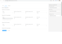
| Configuration | Configuration files based on the popular open source JSON schema concept (similar to the CANedge) |
| Software | Free open source editor tool for easy device configuration (offline/online version available) |
| Safety | CE, FCC, IC and RoHS certified (see the Docs for certificates) |
| Warranty | 1-year warranty |
| Support | Free, fast & high quality support |
| Origin | Denmark |
| SENSOR (input) | |
| Channels | Supports 8 input channels |
| Sensor Types | All 8 input channels support analog, digital and pulse-type sensors |
| Sampling Method | Each input channel samples both the analog, digital and pulse signal of the connected sensor |
| Input Range | Configurable input ranges (0-10V, 0-5V, 0-2.5V, 0-1.25V, 0-0.625V) |
| Range modification is useful e.g. for optimizing quantization resolution and signal amplification | |
| The input channels share input ranges in pairs of two (CH1/CH2, CH3/CH4, CH5/CH6, CH7/CH8) | |
| Resolution | 10 bit |
| Sampling Frequency | Analog inputs: 1 kHz | Digital: 1 kHz | Pulse (frequency/counter): 16 kHz |
| Digital Thresholds | Configurable digital high/low switch thresholds (0-100%) incl. optional dead-zone/hysteresis |
| Pulse Modes | Pulse inputs can be measured as frequencies (reset) or counters (accumulate) |
| Pulse Resolution | Up to 32 bit (4,294,967,294) |
| Protection | Sensor inputs are protected against overvoltage & undervoltage conditions |
| Input Impedance | 136K |
| DATA PARAMETERS | |
| CAN Signals | The module ouputs sensor data via CAN messages/signals (for a full list, see the Docs or DBC file) |
| Analog measurements are output in millivolt (mV) [1000 Hz] | |
| Digital measurements are output as 'actual' (dead-zone, low, high) and 'low'/'high' signals [1000 Hz] | |
| Pulse measurements are output as a frequency/counter value (for reset/accumulate mode) [1000 Hz] | |
| Note: Limits apply to the practical output frequency depending on baud rate, message count etc. | |
| CAN BUS | |
| Channels | 1 x CAN channel |
| Modes | The device can either broadcast the data onto the CAN bus - or provide it on-request |
| Standard | ISO 11898: Compliant with CAN (between 5K and 1 Mbit/s baud rates) and CAN FD (1M, 2M, 4M) |
| Identifiers | Compliant with CAN specifications 2.0A (11-Bit ID) and 2.0B (29-Bit ID) |
| Termination | Termination can be toggled via switch below DB9 connector |
| Retransmission | Retransmission of frames that have lost arbitration or been disturbed by errors |
| Transceiver Protection | Protection: +/- 25kV HBM ESD, +/-12kV IEC ESD, +/-14 V bus fault, short circuit |
| Common mode input voltage: +/-12V | |
| TXD dominant timeout (prevents network blocking in the event of a failure) | |
| CONFIGURATION | |
| Bit Rate | Select between standard bit rates (5K to 1M) or use custom bit-timing |
| Enable/Disable | Individually enable/disable each CAN message |
| Identifier Customization | Individually configure each CAN ID (11-bit or 29-bit) |
| Push/Poll Mode | Individually configure 'trigger' modes for each CAN message (push or poll) |
| Frequency | Individually configure prescaling of each CAN message frequency to lower rates |
| ELECTRICAL | |
| Input Supply | +5V to +26V DC via the DB9 connector (power via pin 1 or pin 9) |
| Alternatively power via USB (for updating firmware/config or for streaming data in real-time) | |
| Power Consumption | Extremely low (<1W) - no risk of battery drainage |
| Protection | Reverse voltage protection on CAN-bus supply |
| Transient voltage event protection on supply lines | |
| MECHANICAL | |
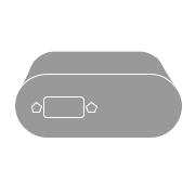
| Enclosure & Weight | Compact aluminium enclosure: 65 x 48 x 24 mm (L x W x H, excl. flanges/connectors), 70 grams |
| Connector (Front) | 1 x Standard D-sub 9 (DB9) connector |
| Connector (Back) | 1 x D-sub 25 (DB25) connector |
| Sensor Supply | Dedicated excitation signals for each channel (~3.3 V, shared max of 100 mA) |
| Pin-Out | See the product manual for the DB9/DB25 connector pin-outs |
| USB | Standard mini USB connector for config/firmware updates and streaming (USB cable not included) |
| LEDs | Module status via 8 external LEDs: Power, CAN bus, Memory, Status, CH1/CH2, CH3/CH4, CH5/CH6, CH7/CH8 |
| Temperature | Operating temperature (CANmod.input module): -25degC to +70degC |
| IP Rating | IP40 |
| Mounting | Module can be mounted via e.g. velcro strips |
The CANmod.input can be installed standalone in any CAN bus system - including e.g. as an add-on for the CANedge.

Add analog/digital/pulse signals to your CAN bus
Need to inject sensor data directly into your CAN bus?
The input-to-CAN module can be used standalone to inject CAN frames with analog/digital/pulse sensor measurements into e.g. your vehicle/machine CAN bus system. The data can be consumed by other CAN nodes on the network - e.g. ECUs, cabin displays, CAN loggers or telematics control units (TCU). To ensure compatibility, you can modify the module output bit rate and CAN IDs via the simple GUI config editor. The module is ideal for e.g. prototype vehicle testing, automotive/industrial development and more.
CAN + sensor data logging & telematics
Need to collect vehicle CAN bus and sensor data via SD/WiFi?
The CANmod.input can be deployed as an 'add-on' module for the CANedge. Simply configure the CANedge to provide a 5V power out via the 2nd port - and connect the CANmod.input via the optional adapter cable. This lets you log e.g. vehicle CAN bus data via channel 1 and time-synced analog/digital/pulse data via channel 2. Data can be offloaded periodically when the asset is within WiFi range - e.g. via a warehouse or garage WiFi router.


On-road vehicle telematics
Need to collect vehicle and analog input data via 3G/4G?
The CANedge3 can upload data while on-the-road via 3G/4G using your own SIM card. You can use a DB9-Y-splitter to power the CANmod.input voltage recorder via the 2nd port of the CANedge3. The uploaded log files can e.g. be visualized in telematics dashboards. Ideal for e.g. 'sensor telematics' use cases like predictive maintenance, remote diagnostics and more. You can of course also daisy chain other CANmod modules like the CANmod.temp temperature-to-CAN module.
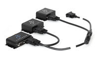
Daisy-chaining input modules
Need a larger number of sensor input channels?
The CANmod.input is extremely simple to setup and configure. With easily customizable CAN frame IDs you can quickly daisy-chain several modules to add 8, 16, 24, ... analog/digital/pulse inputs to your CAN bus (e.g. using DB9-Y-splitters). Every individual input channel can be independently configured - allowing for complete customization. If you wish to record the data to a CAN bus data logger, you can use the CANedge to easily power a full chain of modules via the 2nd port.

The CANmod.input is a small device that supports up to 8 input channels. Each channel can be configured independently and can be used to connect analog, digital or pulse type sensors. The device will read both the analog, digital and pulse measurements for each of the 8 channels - regardless of what sensor is connected. The resulting signals are output via CAN bus frames through the DB9 connector. The DB25 connector allows for connecting the input sensors and also provides a power supply for low power sensor types (~3.3V, max 100 mA across the 8 channels).
The input-to-CAN module can be integrated with any high speec CAN bus system (2.0A, 2.0B) due to the fully configurable bit rates and CAN IDs. Further, it can be powered flexibly from 5-26 V DC, making the installation and wiring very simple for the vast majority of automotive applications.
When used as a standalone device, the analog/digital/pulse data is simply broadcast onto the CAN bus along with the existing CAN traffic. This means that any existing CAN nodes (e.g. ECUs) and CAN hardware (e.g. CAN displays, CAN loggers, CAN interfaces, CAN telematics units) can record the sensor data along with the existing CAN bus traffic. It also means that e.g. OEMs can use the output signals data from the CANmod.input to trigger/control certain behavior in select ECUs.
The CANmod.input can also be used as an add-on for the CANedge CAN bus data logger. In this setup, the CAN bus data from the CANmod.input is recorded - just like data from any other CAN bus. To ease installation, the CANedge can enable a '5V power out' on the 2nd port. This means you can easily connect and power the CANmod.input via the 2nd port (optionally along with other CAN modules like our CANmod.gps). In this setup, the CANedge can log data from e.g. a vehicle via the 1st port and log timesynced analog/digital/pulse data from the CANmod.input via the 2nd port - storing both data sources in the same log file.
The CANmod.input samples the analog, digital and pulse measurement of each input channel - regardless of what sensor is connected.
In some use cases, you may want to simply connect 8 analog sensors and focus on the analog signal. In other cases, you may want to connect 8 digital type sensors (e.g. buttons) and record the data. Or, you may want to mix things up and connect 4 analog, 2 digital and 2 pulse counter type sensors.
Each of the above scenarios can be achieved via the CANmod.input without any configuration changes (though for some use cases you may want to adjust the default input voltage ranges or digital thresholds). In other words, it's 100% plug & play and you can use one device for all your voltage-based measurements. In case you need e.g. 8 digital + 8 analog sensors, you could simply daisy chain two CANmod.input modules together and adjust the output CAN IDs of one of the modules to ensure uniqueness.
When the CANmod.input outputs the sampled data as CAN frames, it will by default output each type of measurement (analog, digital, pulse) for every channel. In the above scenarios you might only care about one of these per input channel (e.g. the digital signals for your digital sensors). However, in some cases it can be useful to be able to monitor each type of measurement for a single channel. For example, you may be interested in the mV signal from an analog sensor for blackbox diagnostic purposes. At the same time, you want to use the digital signal from the same sensor to trigger certain behavior from an ECU. Or, you may be interested in measuring a accumulated pulse counter signal - in which case you may need to review the underlying analog/digital signals to diagnose any unexpected results.
Of course, the CANmod.input lets you easily downscale (or disable) any CAN frames that you're not interested in.
We offer a number of useful adapter cables as options for the CANmod.input:
DB9-DB9/DB9 (Y splitter): This lets you connect one or more modules to the 2nd port of the CANedge - ideal if you e.g. need to log data from both a CANmod.input and a CANmod.gps module.
This adapter can also be used if you wish to connect both the CANmod.input and e.g. a CANedge to the same CAN bus - e.g. for enabling the logging of 2 CAN channels with the CANedge in parallel with logging the input sensor data.
Other adapters: You can use any of our standard DB9 adapter cables with the CANmod.input when using it in standalone mode - thus powering the device via a 5-26 V power supply and sending CAN data directly into your CAN application.
If you wish to add sensor-based analog, digital or pulse data to your CAN bus system or your CAN bus data log files (e.g. via the CANedge), the CANmod.input is the simplest, most compact, flexible and low cost solution.
The device offers extreme flexibility and ease-of-installation by letting you connect either analog, digital or pulse type sensors to each of the 8 channels. For most use cases, no configuration is required - meaning you can simply start measuring sensor data out-the-box.
If configuration is required (e.g. to modify digital switching thresholds, input voltage ranges, pulse modes or CAN bus IDs) this can be done easily via USB and our open source GUI configuration editor. Further, if you need to decode data from the CANmod.input, this can be done easily via the associated DBC file - supported by most CAN bus software tools.
Further, if you need e.g. 16, 24 or 32 input channels, you can simply daisy chain more CANmod.input modules together.
The installation of the CANmod.input depends on your use case - for full details, please refer to the CANmod.input documentation.
The CANmod series can be used as a plug & play extension of the CANedge CAN bus data logger. A popular way of using the module is to power it via the 2nd port of the CANedge - enabling easy logging of sensor data on channel 2, timesynced with CAN bus data from your main CAN application via channel 1.
To use the CANmod with a CANedge, you'll follow the below steps:
- In the CANedge Configuration File, enable the 2nd port 'power out'
- Set the CANedge bit rate on CAN CH2 to match the CANmod (default 250k)
- On the CANmod, enable the 120 ohm CAN termination via the switch below the DB9
- Use a suitable adapter cable to connect the CANmod to the 2nd port of the CANedge (e.g. our DB9-DB9/DB9 adapter)
You can of course also simply connect the CANmod to your main CAN bus network (e.g. powering it directly from the vehicle/machine power supply at 12-26V). In this case, the CANedge can be connected to the same network, allowing it to record the CANmod sensor data along with the regular CAN traffic.
The CANmod.input can stream its sensor data via USB directly into SavvyCAN. However, an often better approach is to connect the CANmod.input's primary CAN interface to one of the CAN channels of a CANsub.2/CANsub.4 and stream the data from there.
This has the advantage that you can directly evaluate the CAN output from the CANmod.input and use the powerful webCAN GUI to analyze and visualize the sensor data - a far more professional experience than SavvyCAN.
It is also a great way to evaluate daisy chains of CANmod.input devices, letting you verify that your custom config files do not produce conflicting arbitration IDs across the chain - and that your DBC files are set up correctly to decode the resulting messages.
The CANmod.input enables measurement of digital input sensors - and produces digital output signals onto the CAN bus, which contain a digital interpretation of the observed waveform. The waveform is digitized according to the configured thresholds.
If you decide to prescale the output message for the digital signals (to reduce the frequency at which the data is output onto the CAN bus), the Digital High / Low signals can be used as 'level detectors'. This can e.g. be used to capture brief events, even if the output frequency is very low (e.g. 1 message per second).
For more details and examples, see the CANmod.input documentation.
No, the CANmod.input is not a CAN logger or able to e.g. push data to a server. For such a use case, you would combine the CANmod.input with e.g. a CANedge. The CAN logger then serves as the platform for recording the analog/digital/pulse data being output by the CANmod.input.
Automotive and industrial use cases deploy a vast number of sensors that produce either analog, digital or pulse outputs. Below we list a small subset:
Gear tooth sensors
Gear tooth sensors enable the detection of gears, flywheels, rack gears, sprockets, and other toothed steel targets - useful for tracking RPM, speed/direction of motion, rotational positions, crane/winch speeds, crankshafts/camshafts and more.
Position/magnetic sensors
Magnetic position sensors like hall effect switches can be used for monitoring e.g. driveshafts, valve positions, clutch positions or orientations of moving components in cars and heavy duty vehicles.
Load cells (e.g. strain gauges)
Pressure sensors and load cells like pre-amplified strain gauges are vital in measuring tension, compression, pressure, torque etc. and are used in e.g. automotive safety, heavy duty payload weight measurement (e.g. for overload determination), wheel power distribution diagnostics and more.
Button sensors
Buttons can be used to inject information about physical events into e.g. a vehicle CAN bus for e.g. post analysis (common in racing/motorsports), diagnostics etc. It can also be used to trigger certain behavior from CAN-based ECUs with the CANmod.input serving as gateway.
Temperature sensors (e.g. thermistors)
Analog temperature sensors like thermistors can be used for high-accuracy industrial/automotive temperature measurement like EGT analyses. Alternatively, see also our CANmod.temp (4 x thermocouple-to-CAN). Analog thermistors have pros & cons vs. thermocouple sensors.
Optical sensors (e.g. infrared)
Optical sensors like infrared (IR) can be used for non-touch temperature measurement, e.g. thermal imaging of tire surface temperatures (vital in motorsports). Light/optical sensors are also used in automotive ambient light sensing, overheight detection etc.
Metal proximity sensors
Metal proximity sensors can be used to e.g. monitor industrial production processes involving metal components or determine the state of e.g. doors/latches via reed switches - useful in theft prevention and automotive safety applications.
Gas sensors (e.g. exhaust gases)
Gas sensors are frequently used within automotive analysis and diagnostics. For example, exhaust gas sensors (CO2, NOx, NH3, ...) are vital to emissions testing, reduction and analysis, while liquified petroleum and propane gas sensors are key in leakage identification.
Do you have any questions?
Contact us