CANopen Explained - A Simple Intro [2026]
Need a simple, practical intro to CANopen?
In this guide we introduce the CANopen protocol basics incl. the object dictionary, services, SDO, PDO and master/slave nodes.
Note: CANopen can seem complex - so this tutorial is a visual intro in layman's terms.
Read on below to fully understand CANopen.
See also our CANopen intro video above - or get the PDF.
In this article

What is CANopen?
CANopen is a CAN based communication protocol.
The CANopen standard is useful as it enables off-the-shelf interoperability between devices (nodes) in e.g. industrial machinery. Further, it provides standard methods for configuring devices - also after installation.
CANopen was originally designed for motion-oriented machine control systems.
Today, CANopen is extensively used in motor control (stepper/servomotors) - and a wide range of other applications:


Medical
X-ray generators, injectors, patient tables & dialysis devices

Six core CANopen concepts
Even if you're familiar with CAN bus and e.g. J1939, CANopen adds a range of important new concepts:
 Communication Protocols
3 protocols for node communication: Master/slave, client/server and producer/consumer
 Communication Objects
Communication objects are used in e.g. configuring nodes (SDOs) or transmitting real-time data (PDOs)
 Device
States
A device supports different states. A 'master' node can change state of a 'slave' node - e.g. resetting it
 Object Dictionary
Each device has an OD with entries that specify e.g. the device config. It can be accessed via SDOs
 Electronic Data Sheet
The EDS is a standard file format for OD entries - allowing e.g. service tools to update devices
 Device Profiles
Standards describe e.g. I/O modules (CiA 401) and motion-control (CiA 402) for vendor independence
The below illustration shows how the CANopen concepts link together - and we will detail each further below.

CANopen history
- 1992: CiA (CAN in Automation) founded
- 1993: Initial development work under Esprit project ASPIC
- 1994: CiA 301 v1.0 released [v4.2.0 in 2011]
- 1996-97: CiA 401-402 released (device profiles)
- 1999: CiA 303-1 v1.0 released (connectors and cabling)
- 2002: CANopen internationally standardized in EN 50325-4
- 2005: CiA 306 v1.3.0 released (EDS, DCF) [v1.4.0 in 2019]
- 2017: CiA 1301 released (CANopen FD)
- 2020: CiA 510 released (mapping CANopen protocols to J1939)
CAN in Automation (CiA) is an international non-profit user/manufacturer group for CAN. The purpose of CiA is to provide a platform for future CAN based specifications and standards. This includes the development of CiA standards (like e.g. the many CiA CANopen standards) and international standardization (such as the standardization of CiA 301 into EN 50325-4.
The role of CiA goes beyond industrial automation and CANopen, however, as the group also promote CAN across automotive, rail, marine and other industries.
In addition, CiA offers services such as conferences, newsletters, testing and more.


CANopen future
CANopen is continuously improved to ensure it stays relevant. This includes the continued development/expansion of CANopen FD to enable CANopen to leverage CAN FD as the lower layer for increased data bandwidth and reliability. In parallel, work will be done on CANopen XL, leveraging CAN XL as the lower layer protocol.
CiA also continues to add new device/application profiles e.g. related to electrification and energy management (such as CiA 418/419). Further, CANopen may increasingly enable device firmware updates via CAN in a secure manner, helping to manage increasing cybersecurity challenges e.g. linked to the rise in IIoT devices connected to CANopen networks.
See e.g. below for further details:
CANopen OSI model & standards
The following is important to understand:
CANopen is a 'higher layer protocol' based on CAN bus.
This means that the Controller Area Network (ISO 11898) enables the communication (like a telephone) for the CANopen protocol (like a specific language).
You can view CANopen from a 7-layer OSI model as illustrated. In the following sections we will cover each part in detail.
The OSI model is a conceptual model standardizing communication functions across diverse communication technologies. Lower layers describe basic communication (e.g. raw bit streams), while higher layers describe things like segmentation of long messages and services like initiating, indicating, responding, and confirming of messages.
CAN bus represents the two lowest layers (physical and data link). This means that CAN simply enables the transmission of CAN frames, thus playing the same role in CANopen as it does in e.g. the J1939 protocol.
Note that the CANopen protocol is often displayed in ambigious ways when it comes to the 7 OSI layers. The official CiA 301 standard simply illustrates CANopen as covering the 5 layers above the physical and data-link layers (which are covered by CAN) - but with no explicit distinction between the 5 layers. In some interpretations, CANopen is indicated as being purely an 'application layer' protocol, i.e. covering layer 7 of the OSI model only. To some extent, our illustration matches this, but with the primary distinction that we consider the multi-frame SDO transfer protocols to be related to the transport layer of the OSI model (similarly to the role of ISO 15765-2 aka ISO TP in e.g. UDS/OBD).
We also consider the EDS/DCF (CiA 306) to not be related to the 7 OSI layers, but rather a separate supplement to the standard - similar to the role of CAN database (DBC) files in various other CAN protocols and LIN Description Files (LDF) in LIN bus.
In this article we primarily focus on CANopen based on Classical CAN (CANopen CC). However, it is worth noting that as CANopen FD is also defined as per CiA 1301, using CAN FD as the lower layer. The CiA 1301 standard enables support for longer PDOs (utilizing the increase from 8 data bytes to 64 data bytes) and also introduces the Universal SDO (USDO). However, in this tutorial we primarily focus on CANopen on Classical CAN as per CiA 301.

CANopen vs. CAN bus
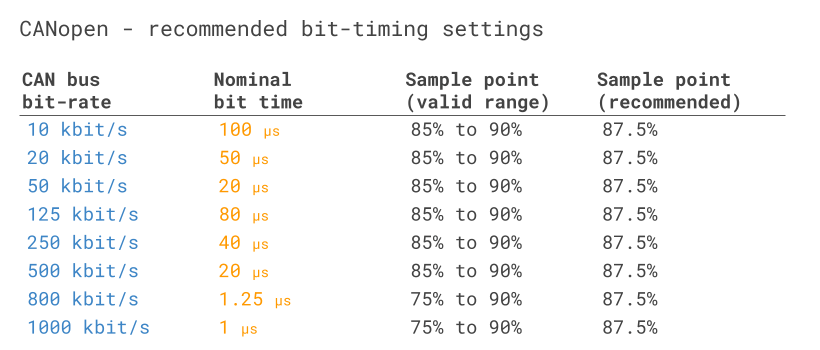
As evident from the OSI model, CANopen is normally based on CAN bus, with ISO 11898 specifying the physical layer and data link layer. CiA 301 provides guidelines related to bit-timing as per the illustration with the goal of maximizing interoperability of CANopen devices. Further, the standard states that CANopen is based on 11-bit CAN IDs and that support for 29-bit IDs is not required - and as a result, the normal convention is to use 11-bit IDs in CANopen.
It is worth noting that CANopen can be adapted to other lower layer protocols than CAN (e.g. EtherCAT, Modbus, Powerlink) - although CAN is by far the predominant basis for CANopen in practice. The most common alternative is CANopen over EtherCAT (CoE), which is often used in industrial automation.
CANopen cable connectors [CiA 303-1/CiA 106]
The formal CANopen standard does not specify physical connectors (in contrast to e.g. J1939 and OBD2). However, the related CiA 303-1 (later CiA 106) does offer recommended pin-outs for CANopen (and CAN in general), including below:

#1 D-SUB 9-pin connector (DB9)
The DB9 connector is one of the most commonly used general purpose CANopen connectors and the first connector recommended in the original CiA 303-1 document with the pinout illustrated. This connector often enables external devices to connect to CANopen networks. Further, it has today become the de facto standard for general purpose CAN bus hardware, including e.g. our own CANedge/CANsub/CANmod series.
DB9 adapters
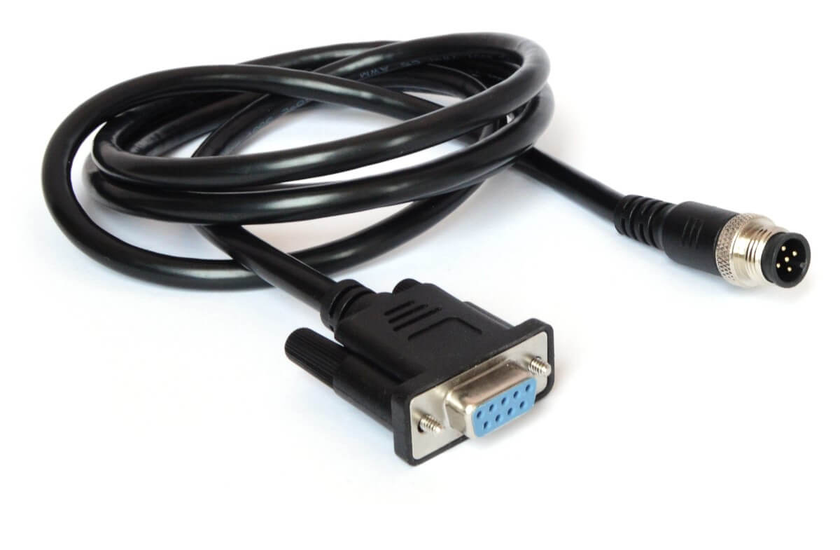
#2 M12 5-pin connector (industrial)
Another commonly used connector is the M12 5-pin (micro) connector with the illustrated pinout. This connector is used both in CANopen and NMEA 2000 applications, offering better resistance to harsh environments vs. the DB9 connector.
DB9-M12 adapter
#3 Open wire connector
In addition to the above connectors, CANopen devices are often connected via open style connectors. As a result, DB9 to open wire adapter cables can be useful in enabling devices with DB9 connectors to be connected to such terminal sockets.
DB9-generic adapterThe CANopen frame and COB-ID
To understand CANopen communication, it is useful to first understand the CANopen CAN frame:
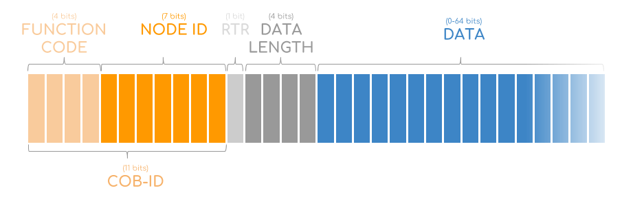
The 11-bit CAN ID is referred to as the Communication Object Identifier (COB-ID) and is split in two parts:
- Function code: 4 bits reflect the 'functionality' of the message
- Node ID: 7 bits reflect the node ID (between 1 and 127)
The function code relates to different 'communication objects' used in CANopen (more on these later).
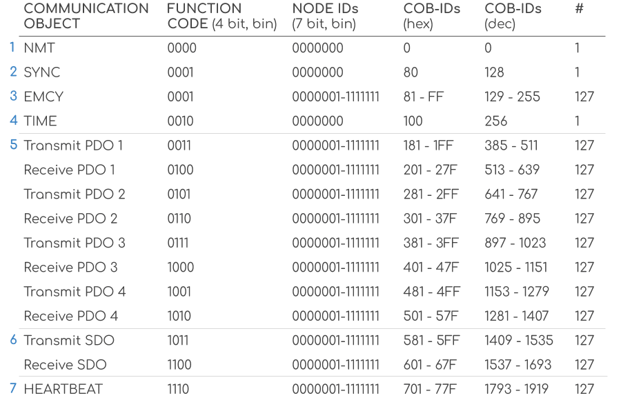
For example, the COB-ID 0x0 is used for a special service called NMT, while the range of COB-IDs from 0x181 (0b00110000001) to 0x1FF (0b00111111111) are used for 'Transmit PDO 1'. Notice how the first 4 bits are constant, while the remaining 7 bits go from 1 to 127. This reflects how up to 127 separate CANopen nodes may be broadcasting a 'Transmit PDO 1' message, each of them including their unique node ID in the COB-ID (i.e. CAN ID). Note that the COB-ID table reflects the pre-defined generic allocation set, which may be customized.
It is important to note that the mapping of COB-IDs shown in the table reflects a pre-defined generic mapping, intended to reduce the need for customizing each node of a CANopen system.
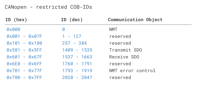
Some of the listed COB-IDs are restricted from modification including the NMT (0x00) and SDOs (0x581 to 0x67F) - see also the table of restricted COB-IDs.
In contrast, the COB-IDs for SYNC, TIME, EMCY and PDOs may be customized during initialization. In particular, as we will cover in the section on PDOs, if no modification is made to the TPDO/RPDO mapping, the result would be that various CANopen nodes might be producing messages using the pre-defined Transmit PDO COB-IDs - but no nodes on the bus would be configured to listen to this traffic (since none of the Receive PDO COB-IDs by default overlap with any of the Transmit PDO COB-IDs).
 Generic pre-defined COB-ID allocation
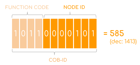
Example: Transmit PDO for Node 5 using generic COB-ID mapping
CANopen COB-ID converter
Online CANopen COB-ID converter
Our COB-ID converter lets you quickly look up a CANopen COB-ID to return basic details incl. function code and node ID.
CANopen communication protocols and objects
In CANopen networks several devices need to communicate.
For example, an industrial setup may have a robot arm with multiple servomotor nodes and a control interface/PLC node.
To enable this, three communication protocols are used:


Master/Slave
One node (e.g. the control interface) acts as master. It sends/requests data from the slaves (e.g. a servo motor). This is used in e.g. diagnostics, configuration or state management. There can be 0-127 slaves.
Service example: NMT

Client/Server
A client sends a data request to a server, which replies with the requested data. Used e.g. when a master needs data from the OD of a slave. A read from a server is an 'upload', while a write is a 'download'.
Service example: SDO

Consumer/Producer
Here, the producer node broadcasts data to the network, which is consumed by the consumer node. The producer either sends this data on request (pull model) or without a specific request (push model).
Service example: PDO

In addition, CANopen specifies a number of communication objects that serve different use cases. Each communication object represents a pre-defined structure in the CANopen communication, including e.g. dedicated COB-ID(s) as illustrated in the previous section. We will detail each type in the following sections, with particular focus on the SDO and PDO:
- SDO: Service Data Object
- PDO: Process Data Object
- NMT: Network Management Objects
- SYNC: Synchronization Object
- TIME: Timestamp Object
- EMCY: Emergency Object
- HEARTBEAT: Heartbeat Object
SDO (Service Data Object) - configuring the CANopen network
What is the CANopen SDO?
The SDO (Service Data Object) allows a CANopen node to read/write values of another node's object dictionary (OD) over the CAN bus.
The SDO requests/responses are sent via the 'client/server' protocol. Specifically, an SDO 'client' initiates the communication with an SDO 'server'. The purpose can be to update an OD entry ('SDO download') or read an entry ('SDO upload'), which allows for e.g. node configuration and diagnostics.

Example: SDO download CAN frame
The client node can initiate an SDO download to a server with node ID 5 via below CAN frame:
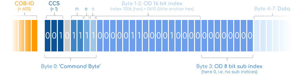
- First, COB-ID 0x605 reflects the use of an 'SDO receive' (COB-ID 0x600 + node ID 0x5).
- The CCS (client command specifier) is the transfer type (e.g. 1: Download, 2: Upload)
- n is the #bytes in data bytes 4-7 that do not contain data (valid if e & s are set)
- If set, e indicates an 'expedited transfer' (all data is in a single CAN frame)
- If set, s indicates that data size is shown in n
- Index (16 bits) and subindex (8 bits) reflect the OD address to be accessed
- Finally, bytes 4-7 contain the data to be downloaded to node 5
In many ways, the CANopen SDO can be compared to other CAN based diagnostic protocols, such as OBD (On-Board Diagostics) and UDS (Unified Diagnostic Services). These protocols are extensively used in automotive deployments to enable diagnostics and configuration in vehicles. Similar to CANopen SDOs, they involve a request/response type work flow, where specific nodes can be targeted via specific CAN IDs. As with CANopen SDOs, a client tool can e.g. request the current data value of a specific parameter, with OBD2 Parameter IDs (PIDs) playing a similar role to the CANopen object index and subindex.
In addition, as we will cover below, CANopen SDOs can be communicated in larger segments/blocks across multiple frames, which is very similar to how OBD/UDS communication often involves multi-frame communication as per ISO TP (ISO 15765-2).
SDO variants: Expedited, segmented and block transfer
The CANopen SDO protocol specifies 3 different transfer methods:

1: Expedited transfer
This transfers the full payload in a single initialization/confirmation flow between the client and server, ideal for small 1-4 byte data payloads

2: Segmented transfer
This involves an initialization/confirmation step after which segments of up to 7 data bytes can be transferred (each segment requiring a confirmation message)

3: Block transfer
This is useful for large data transfers. Here, a confirmation is only required after each 'block' of messages (up to 127 segments per block), reducing overhead
Below we illustrate each SDO transfer type via raw CANopen traces (with detailed explanations below):
Example 1: SDO expedited transfer (download + upload)

This trace shows a client node that uses SDO request messages with ID 0x601 to download data to a server with node ID 1. Specifically, data is downloaded to the node object dictionary at index 0x1601 across sub indices 0x04, 0x05, 0x06 and 0x00. The second half of the trace shows the client performing an upload request to read data from the device object dictionary at index 0x3001 across sub-indexes 0x10, 0x11 and 0x01. Notice how the command byte (byte 0) is shown in binary form to make it explicit how this byte controls the type of request/response - including whether to perform a download or upload, as well as the transfer type.
As evident, the expedited transfer method is very simple, but carries a lot of overhead.
Example 2: SDO segmented transfer (upload + download)
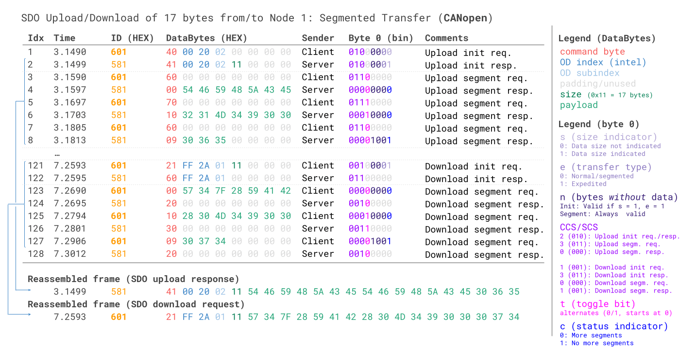
This trace shows the normal/segmented SDO transfer method, including both an SDO upload and SDO download example. In both cases, the client sends an initiation request message. Notice here how the transfer type bit is set to 0 instead of 1, reflecting that expedited transfer is not to be used. Further, note how the data payload length (0x11 = 17 bytes) is included in the initiation by the server (for the SDO upload) and client (for the SDO download).
Once the initiation request/response has been performed, each segment is communicated - and every transmitted segment is confirmed. In the case of the SDO upload, the client thus requests the first segment (with an empty payload except the command byte) and the server responds with the first 7 bytes of the payload. This continues until all 17 bytes are uploaded. Notice how the 'toggle bit' of the command byte alternates between 0 and 1 throughout. In the final message from the client, it sets the 'status indicator' bit from 0 to 1 to communicate that no further segments will be sent.
The SDO download works similarly, except that here the client is the one transmitting the data payload to the server.
As with any other CAN based transport protocol, one may re-assemble the segmented payload into a single CAN frame. The exact method for doing this is up to the software/API/application, so we mainly provide an illustrative example.
Example 3: SDO block transfer (upload)
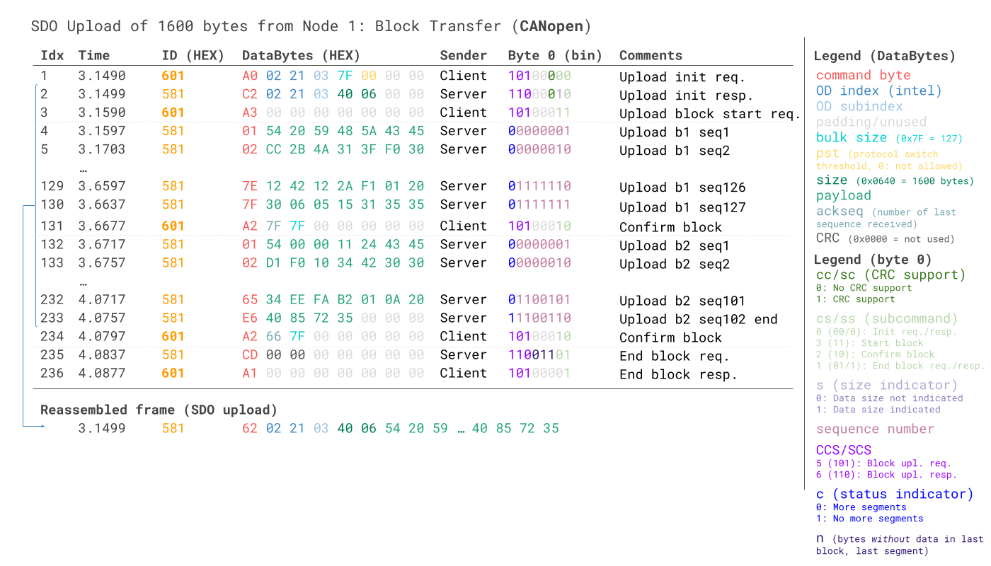
The SDO block transfer method is powerful for communicating very large payloads. In the example, a client is looking to read data from the node OD at index 0x2102 subindex 03. The client requests for this to be sent via block transfer, as indicated by the 'client command specifier' (CCS) being set to 5. As part of this, the client informs the server about the maximum block size in number of frames (between 1 and 127). Further, the client specifies via the 'CRC support' bit whether a checksum should be calculated on the overall payload and sent in the final frame by the server (in this example the CRC is not calculated).
As in segmented transfer, the communication starts with a simple initiation request/response. However, the SDO upload block transfer also requires that the client explicitly initiates the transfer by sending a 'start command' as per frame 3 with the command byte subcommand value 3 (0b11).
Following this, the server transmits a total of 127 frames of data, each time increasing the sequence counter in byte 0 by 1. In response to this 'block' of segments, the client sends a confirmation frame (frame ID 131). To ensure alignment, the client includes the sequence number of the last frame received (which must match the server's sequence number).
This process continues until the final block which only contains 102 frames from the server. In the last frame of the block, the server sets the 'status indicator' to 1 to indicate that no further data is to be sent. As before, the client confirms the block, after which the server sends an 'end block' request frame. This frame may also include the 2-byte CRC value if supported. After this frame, the client sends an 'end block' response frame.
Example 4: SDO block transfer (download)
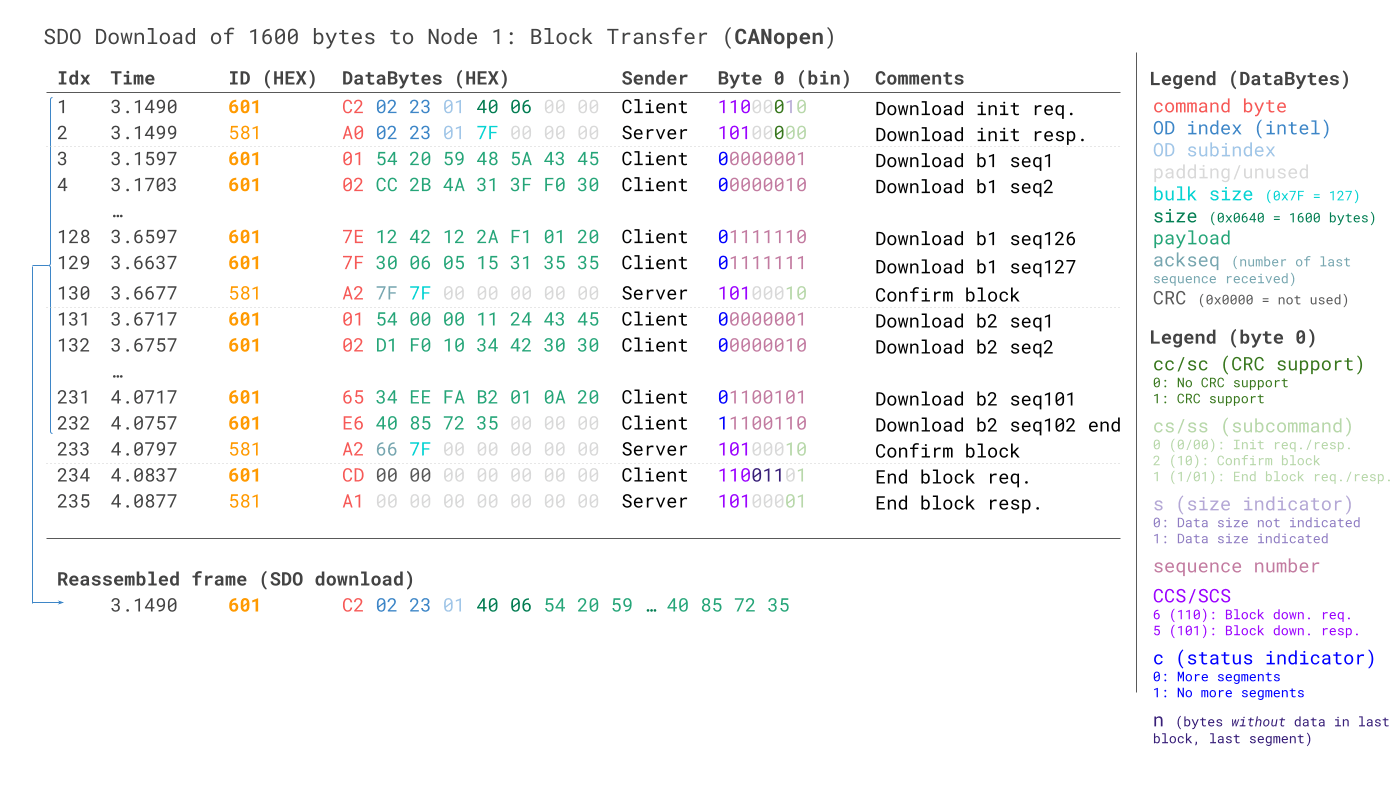
The SDO download block transfer concept is overall similar to the previous example, except that the 'start block' frame is not included.
SDOs are flexible, but carry overhead - making them less ideal for real-time operational data. This is where the PDO comes in.
PDO (Process Data Object) - operating the CANopen network
What is the CANopen PDO?
The CANopen PDO (Process Data Object) is used for efficient transfer of real-time operational data across CANopen nodes.
For example, PDOs may carry pressure data from a pressure transducer or temperature data from a temperature sensor.
But wait: Can't SDOs achieve this?
Yes, the SDO could be used - but with much more overhead. For example, let's say a CANopen node needs two 4-byte parameter values (e.g. "DC Current" and "Velocity") from node 5. To get this via expedited SDOs, it would require 4 CAN frames (2 requests, 2 responses), as each SDO upload response can only carry 4 bytes.


In contrast, a PDO can contain 8 bytes of data and multiple object parameter values in a single frame. In the example, what would require 4 SDO frames could be done with 1 PDO frame.
For PDOs, the 'consumer/producer' protocol is used. A producer 'produces data', which it transmits to one or more 'consumers' using a transmit PDO (TPDO). Conversely, it may receive data from the consumer via a receive PDO (RPDO).
PDOs may be sent via synchronous transmission (in response to a SYNC) or event-driven transmission (e.g. periodically). Further, PDOs may be triggered via a remote CAN frame (RTR) from a consumer, though this is no longer recommended.
Isn't the PDO service a bit similar to J1939 PGNs & SPNs?
Yes, to some extent this is similar to how a specific J1939 parameter group (PG) will contain multiple SPNs/signals (aka data parameters) in the 8 data bytes. The J1939 CAN frame does not need to waste data bytes on "decoding" information because this is known by the relevant nodes (and by external tools via e.g. J1939 DBC files or the J1939 PDF standards). The wrinkle is that in CANopen, these 'PDO mappings' are often configurable and can be changed during the creation of the DCF and/or via the SDO service.
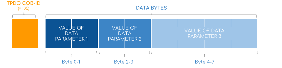
PDO COB-ID mapping
As explained previously, CANopen devices will typically ship with a pre-defined generic configuration of their COB-IDs, including for any receive PDO or transmit PDO objects they may have mapped in their object dictionary.
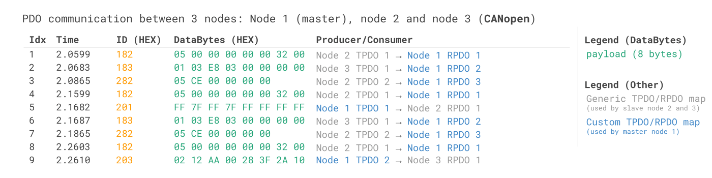
However, if all CANopen nodes use the generic PDO COB-IDs, none of them would consume any TPDOs. Therefore, a practical CANopen system will involve some customization of PDO COB-IDs. In the example illustration, nodes 2 and 3 use generic COB-IDs for their TPDO/RPDO objects, while node 1 is customized to consume the TPDOs from node 2 and 3 and to produce a PDO for each of them (mapping to their generic RPDO1 objects).

Example: Event-driven PDO messages
Below we show three CANopen nodes broadcasting PDOs (using the above COB-ID mapping):
Other CANopen communication objects
In this section, we briefly outline other important CANopen communication objects:


#1: NMT (Network Management Objects)
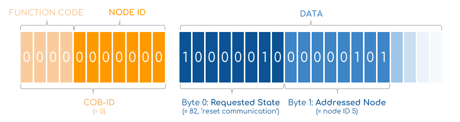
The NMT objects follow the master/slave protocol. An NMT master controls the 'state' of slaves through NMT commands. To change the state of a device, the NMT master sends a message with COB-ID 0x0, which all slave nodes process. The 1st data byte contains the requested state, while the 2nd CAN data byte contains the node ID of the targeted node. Node ID 0 indicates a broadcast command. The requested state request values include 0x01 (operational), 0x02 (stopped), 0x80 (pre-operational), 0x81 (reset application) and 0x82 (reset communication).
Below illustrates an example CANopen NMT frame, specifying that node 5 should reset communication.

#2: SYNC (Synchronization Object)
The SYNC message follows the producer/consumer protocol. A producer (typically the CANopen master) broadcasts the SYNC message periodically with a high-priority ID (COB-ID 0x80). This allows CANopen SYNC consumers to synchronize the timing of when to e.g. broadcast data via Transmit PDOs.

#3: TIME (Timestamp Object)
The TIME message follows the producer/consumer protocol and provides a network-wide clock to be distributed. The producer broadcasts the TIME message with the COB-ID 0x100 and a 6-byte payload: 4 data bytes contain time in ms after midnight and the next 2 bytes contain the number of days since January 1, 1984.

#4: EMCY (Emergency Object)
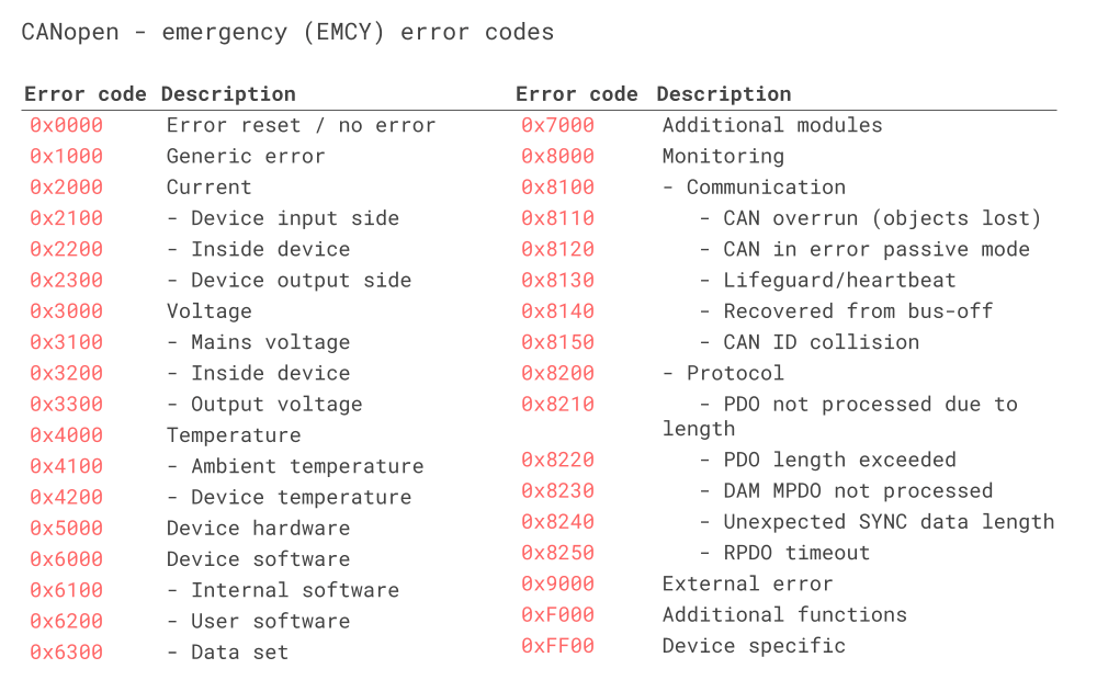
The emergency object follows the producer/consumer protocol and is used in case a device experiences a fatal error (e.g. a sensor failure), allowing it to indicate this to the rest of the network. The affected node sends a single EMCY message with COB-ID 0x80 + node ID (e.g. 0x85 for node 5). The data bytes contain information about the error, including a 2-byte error code (see below), a 1-byte error register and up to 5 bytes of manufacturer specific error information.
The below table of error codes is from CiA 301. Additional error codes may be specified in device profiles as per CiA 4XX. Support for EMCY is optional, but if a device does support it, it must support at least the error codes 0x0000 and 0x1000.


#5: HEARTBEAT (Heartbeat Object)
The heartbeat message follows the producer/consumer protocol. CANopen slaves may periodically broadcast a heartbeat message (e.g. every 100 ms) with COB-ID 0x700 + Node ID (i.e. 0x705 for node 5). The payload contains the node state in the 1st data byte (boot-up, pre-operational, operational, stopped). This allows a consumer (e.g. the master) to react quickly if a node fails to broadcast its heartbeat within a set time limit.
Example: NMT, SYNC, TIME, HEARTBEAT and EMCY
Below we show how the various CANopen communication objects may look in a CAN bus trace:
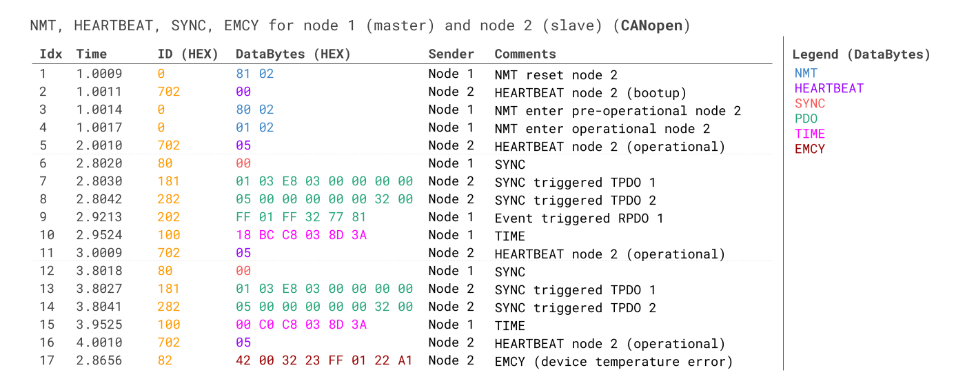
In this CANopen trace two nodes are communicating, a master (node 1) and a slave (node 2). The trace starts out with the master resetting node 2 via an NMT reset command targeting node 2 specifically. After this, node 2 communicates its state via the HEARTBEAT message (with a value of 0x00, indiacting bootup). Node 1 then instructs node 2 to go into pre-operational and then operational mode. After this, node 1 transmits a periodic SYNC message to trigger two TPDO messages from node 2 containing data on various pre-mapped objects. Node 1 also produces a TIME message every 1 second. After a brief period of communication, node 2 reports an error via the EMCY message. The first two bytes contain the error code, which in this case is 0x4200. By looking this up in the error code table, we can see that the error is related to the device temperature.
CANopen Object Dictionary (OD)
All CANopen nodes have an object dictionary (OD) - but what is it?
The object dictionary is a standardized structure containing all parameters describing the behavior of a CANopen node.
OD entries are looked up via a 16-bit index and 8-bit subindex. For example, index 1008 (subindex 0) of a CANopen-compliant node OD contains the node device name.
Specifically, an entry in the object dictionary is defined by attributes:
- Index: 16-bit base address of the object
- Object name: Manufacturer device name
- Object code: Array, variable, or record
- Data type: E.g. VISIBLE_STRING, or UNSIGNED32 or Record Name
- Access: rw (read/write), ro (read-only), wo (write-only)
- Category: Indicates if this parameter is mandatory/optional (M/O)

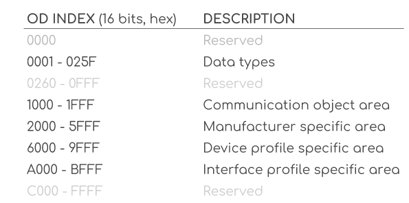
OD standardized sections
The object dictionary is split into standardized sections where some entries are mandatory and others are fully customizable.
Importantly, OD entries of a device (e.g. a slave) can be accessed by another device (e.g. a master) via CAN using e.g. SDOs.
For example, this might let an application master change whether a slave node logs data via a specific input sensor - or how often the slave sends a heartbeat.
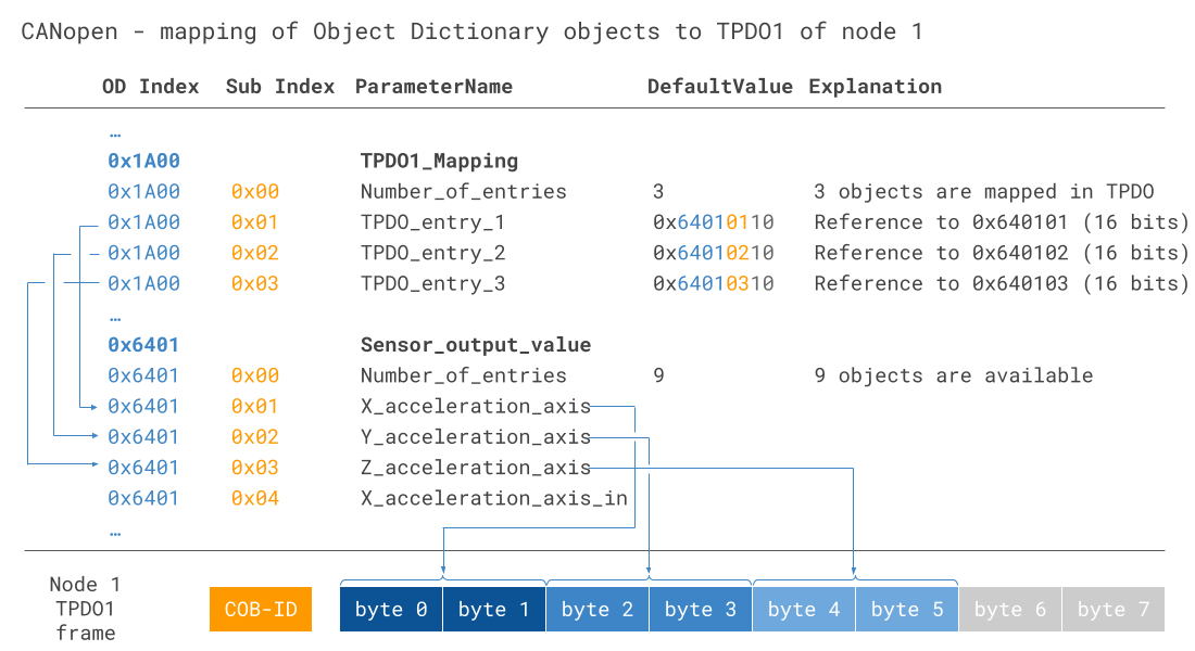
Example: OD mapping of Transmit PDO
On way of illustrating the role of the OD is to consider how it may link to the payload mapping of a device transmit PDO. Such mappings are defined within the OD itself in the OD indices 0x1A00 to 0x1BFF. As per the illustration, index 0x1A00 subindex 0x01 may contain the 4-byte 'DefaultValue' 0x64010110. This corresponds to the object index 0x6401 and subindex 0x01 which is the OD entry of a specific parameter (in this case X acceleration). The last byte 0x10 reflects the parameter bit length, i.e. 16 bits in this example.
A CANopen device typically comes with a pre-defined TPDO/RPDO mapping as part of its object dictionary, though in most cases this is configurable through the use of SDOs or by modifying the device object dictionary (more on this below).
Electronic Data Sheet (EDS) and Device Configuration File (DCF) [CiA 306-1]
To understand the OD, it is helpful to look at the 'human-readable form': The Electronic Data Sheet and Device Configuration File.

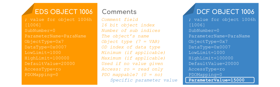
The Electronic Data Sheet (EDS)
In practice, configuring/managing CANopen networks is done using software/API tools. To simplify this, CiA 306-1 defines an INI file format, acting as the 'template' for the OD of a device - e.g. the 'ServoMotor3000'. The EDS is provided by the device vendor and contains info on all device objects, incl. e.g. supported parameters and default TPDO mappings.
Device Configuration File (DCF)
Assume a factory has bought a ServoMotor3000 to integrate into their conveyor belt. In doing so, the operator edits the device EDS with integration-specific details, e.g. specifying the device bit-rate and node ID. This modified EDS can be exported as a Device Configuration File (DCF) to enable the device (e.g. the ServoMotor3000) for integration into a specific network.
Reviewing real EDS/DCF examples is one of the best ways to really understand the object dictionary of CANopen - see e.g. the difference between an EDS and DCF object entry below. Check out our intro to CANopen EDS files for further details.
Example: Visualizing TPDO mapping
The most common way to configure CANopen devices is to use an EDS editor to load the related EDS or DCF for the device. An example modification may be to customize the mapping of various transmit PDOs supported by the device. Most EDS editors also support visualization of the PDO payloads and how object dictionary entries are mapped to the PDO data bytes.
Our EDS intro provides an overview of popular editors.

How to log and decode CANopen data
In this section we explain how you can record and decode CANopen data using the CANedge CAN bus data logger (or the CANedge2 / CANedge3 to offload data via WiFi/LTE).
#1: Select a CAN bus data logger
The CANedge1 is ideal if you simply need to log data to an SD card - like a CANopen blackbox. This lets you e.g. capture intermittent issues on your network for diagnostics.
Alternatively, the CANedge2 (WiFi) or CANedge3 (3G/4G) lets you auto-upload data to your own server, enabling e.g. remote troubleshooting, event detection and predictive maintenance.
If you need to stream CANopen data in real-time via USB/Ethernet, see our CANsub.2/CANsub.4 + webCAN software.
#2: Connect to your CANopen bus
As explained, CANopen systems may provide standard DB9 connector interfaces as per CiA 306-1, in which case you may connect the CANedge directly (or with a DB9-DB9 cable). If your network provides an M12 or open terminal interface, you can alternatively use an M12-DB9 adapter or generic-DB9 adapter.
#3: Sniff traffic and/or request data
Often you may simply want to sniff existing CANopen traffic. If so, you can deploy the CANedge in 'silent mode' to record all CAN frames (optionally using filters to reduce file size).
In some cases, you may want to request specific parameter data. To do this, you can configure the CANedge to transmit custom CAN frames, effectively making the CANedge an SDO client. This also means that you can effectively use a CANedge2/CANedge3 as a remote CANopen gateway.
In either case, the result will be log files containing raw CANopen data, which you can view in e.g. the asammdf GUI (as illustrated) or tools like Vector CANalyzer or PCAN-Explorer.
You can also load the data via our python-can integration to e.g. leverage popular libraries like Python for CANopen.

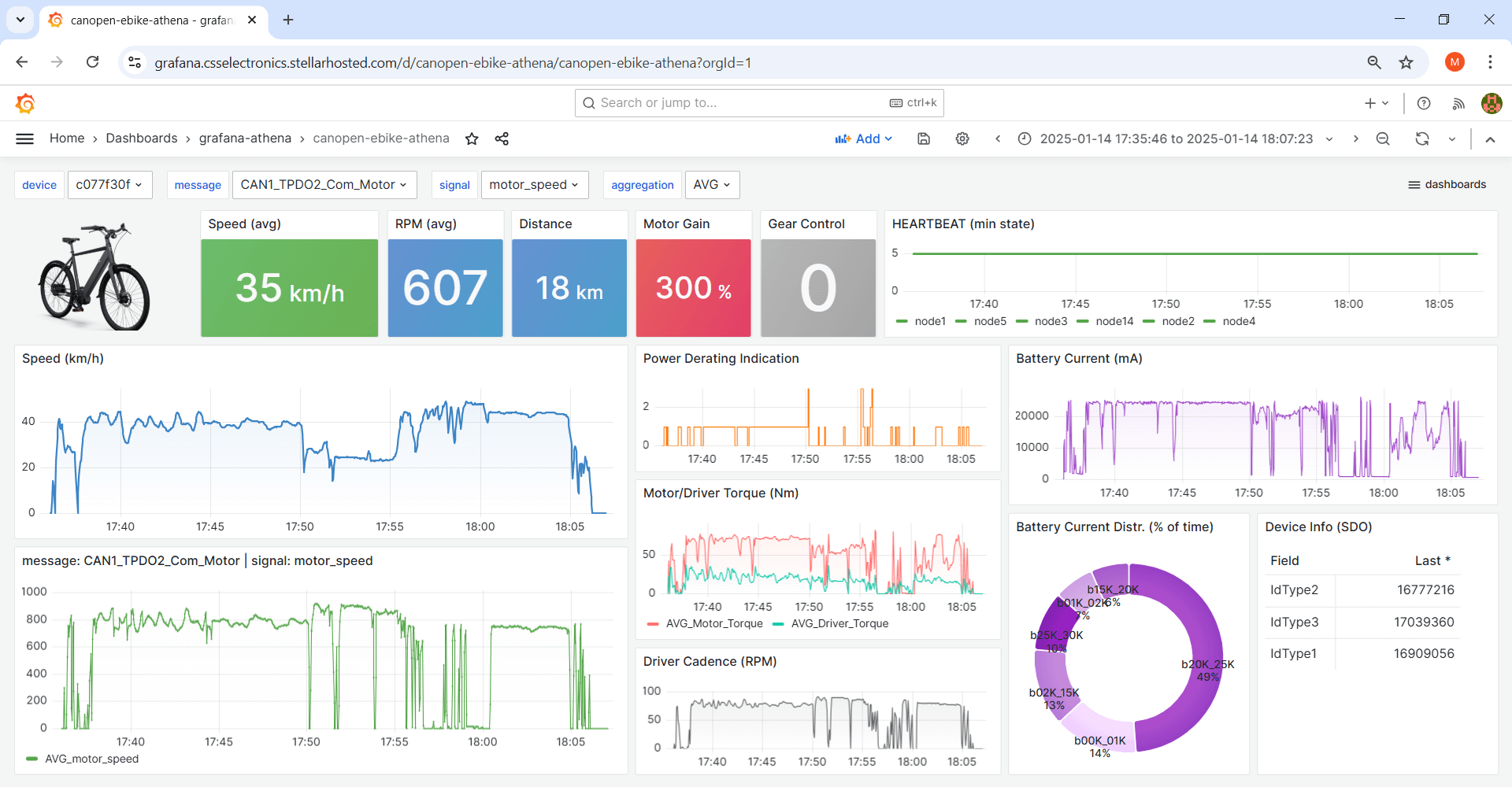 Data can e.g. be visualized in dashboards like our
CANopen playground
Data can e.g. be visualized in dashboards like our
CANopen playground
#4: Decode CANopen data via EDS/DBC
Finally, if you want to analyze/visualize the recorded CANopen data, it can be useful to decode the data into physical values. This allows you to e.g. create timeseries plots of parameters like current, temperatures, angles etc. and incorporate this data into dashboards - or use it in statistical analyses.
Most CAN software/API tools support DBC files (CAN databases) for loading the decoding rules required to translate raw CAN bus data into physical values. However, most CANopen devices instead come with the EDS/DCF file and rarely a DBC file.
Luckily, you can convert your EDS file to a DBC file in a few steps as explained in our intro to CANopen EDS files.
You can of course contact us for further guidance.
CANopen data logging - use case examples
Below you can learn more about various CANopen data logging use cases:

Logging CANopen node data
Generally, logging CANopen data can be used to e.g. analyze operational data. WiFi CAN loggers can also be used for e.g. over-the-air SDOs
CANopen logger
Warehouse fleet management
CANopen is often used in EV forklifts/AGVs in warehouses, where monitoring e.g. SoC helps reduce breakdowns and improve battery life
warehouse telematics
Predictive
maintenance
Industrial machinery can be monitored via IIoT CAN loggers in the cloud to predict and avoid breakdowns based on the CANopen data
predictive maintenance
Machinery diagnostic blackbox
A CAN logger can serve as a 'blackbox' for industrial machinery, providing data for e.g. disputes or rare issue diagnostics
can bus blackboxFor more intros, see our guides section - or download the 'Ultimate Guide' PDF.
Need to log/stream CANopen data?
Get your CAN logger/interface today!


