LIN Description File (LDF) Explained - A Simple Intro [2026]

Need a simple intro to LIN Description Files (LDF)?
In this tutorial we explain the LIN description file, incl. the basics, syntax, software tools - and the link to CAN bus DBC files.
To get practical, we also include raw LIN bus data and LDF/DBC files - which you can load in free open source software/API tools.
Get ready to fully understand LIN description files!

What is a LIN Description File (LDF)?
The LIN Description File (LDF) is a text file that describes a complete Local Interconnect Network (LIN) cluster as per ISO 17987-1. In particular, the LDF includes the following info:
- General (protocol, bit-rate, time base, ...)
- Nodes (master, slaves, node addresses)
- Schedule tables (frames, time slots, ...)
- LIN frames (ID, type, ...)
- LIN signals (names, encoding, ...)
The LIN description file can be loaded by LIN software/API tools for managing/analyzing the communication of the related LIN cluster. For example, an LDF may allow a LIN-USB interface to act as a LIN master in a cluster. Or, it can be used in decoding and visualizing recorded LIN bus data.


LIN Node Capability Files (NCF)
A LIN cluster often includes LIN nodes from different manufacturers. Typically, each manufacturer provides a Node Capability File (NCF) for any off-the-shelf node. The NCF is a text file with a very similar structure to the LDF - but limited to the individual LIN node properties (rather than a full cluster).
Most LDF editors can import multiple NCFs to create a new LIN description file, thus enabling the creation of a custom LIN cluster as part of a design phase.
Sometimes a manufacturer instead provides an LDF for an off-the-shelf node. Editors can load this LDF, export the NCF and then import this into other LDFs as needed.
LDF syntax
In practice, you will most often use a software editor to load/create/edit an LDF. This is recommended to ensure valid syntax and avoid consistency errors.
However, to fully understand LIN description files it is useful to look at the raw syntax. In this section we break down the most important sections of the LDF with outset in an example LDF.
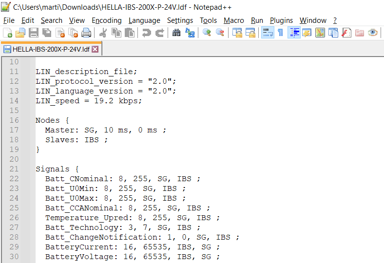

1: Global
The global section of the LDF describes details on the LIN protocol/language version (e.g. 2.0, 2.2, ...) and the bit-rate (e.g. 19.2 kbps). The version number is important as there can be LDF syntax-related changes, in particular between LIN 1.x and 2.x.

2: Nodes
This lists the names of the LIN master and slaves in the cluster. In the example, there is a single master (SG) and a single slave (IBS), but in most practical LIN clusters the list would include multiple LIN slaves. This section also details the time_base and jitter in ms. The time_base is typically 5 ms or 10 ms, while the jitter value is typically between 0 ms and 0.5 ms.

3: Node_attributes
This section includes all necessary information on individual LIN slave nodes, incl. the protocol revision, the default node address (NAD) and the name of the response_error signal used in LIN bus error detection. The configurable_frames section includes all frames (unconditional, event triggered, sporadic) which are processed by the slave node (rather than ignored).

4: Schedule_tables
This section of the LDF describes a set of available schedule tables, with different tables available for different use cases - including often one for 'normal operation'. Each table has a unique name and contains a list of LIN frames followed by a frame slot time (e.g. 50 ms).
Notice that if the time_base of the LDF is set to 10 ms, a frame slot time must be an integer multiple of this - and thus it cannot be e.g. 15 ms. In the example shown, each frame slot is 50 ms. Notice also that some frames are repeated throughout the table as a way of achieving a higher frequency for select signals.

5.1: Frames
This section lists all unconditional LIN frames defined in the LIN cluster. Each entry includes a name (e.g. IBS_SOC), frame ID in decimal form (e.g. 34), the LIN node publishing the frame (e.g. IBS) and the length (e.g. 6 bytes).
In addition, this includes a list of the encoded signals and the start bit of each signal. Note that similar sections may exist in the LDF with details for sporadic and event triggered frames. See below for examples of the syntax:

5.2: Sporadic_frames
This lists sporadic frames (if any). Each sporadic frame includes a list of unconditional frame names, referencing frames defined in the Frames section. Naturally, the referenced frames need to be published by the LIN master, as per the specification of sporadic frames. Note also that these unconditional frames must not be broadcast by the master in the same schedule table as the sporadic frame is defined in. Many LDFs (including our sample) do not include this frame type.

5.3: Event_triggered_frames
This lists event triggered frames (if any). Here, the frame references a separate collision resolution table that will come into effect in the case of collisions, ensuring that the unconditional frames are sent sequentially. The ID refers to the frame ID of the event triggered frame, which is followed by a list of unconditional frames, which again refer back to the more detailed definitions found in the Frames section. Many LDFs (including our sample) do not include this frame type.

6: Signals
This section lists all signals across the defined frames, including the signal length (in bits), the default/initial value, the node publishing the signal and a list of nodes receiving the signal.
Note how e.g. the signal Batt_U0Min is published by the LIN master. This signal is part of the frame SG_BatteryConfig, which is used by the LIN master to transmit configuration-related information to the HELLA IBS LIN slave. In contrast, the signal SOC is part of the frame IBS_SOC, which is published by the LIN slave and subscribed to by the LIN master.

7: Signal_representation
This section links a logical signal (e.g. SOC) to the physical encoding representation of this signal (e.g. Enc_SOC). In most cases there is a simple 1:1 mapping between these two concepts, but sometimes a single encoding definition is used across multiple different signals, as is e.g. the case for Enc_Batt_CNominal in the LDF, which is used for both the signals Batt_CNominal and Batt_CNominal_coded. The 'Enc_' prefix used in the example LDF is arbitrary.

8: Signal_encoding_types
This section provides the information required to decode raw LIN signals into human-readable physical values (%, degC, ...). For the example signal SOC we can look up the encoding via Enc_SOC. Here we see a list of physical_value and logical_value entries. To calculate the physical value of a signal, the below linear formula is used:
This formula applies in the raw_value min-max range of the physical_value entry. For example, the 1st entry applies only to the range of 0 to 1500 (0x0000 to 0x05DC). In this range, the formula can be used with a scale of 0.1 and an offset of 0 with % as the unit. The second physical_value range is 1501 to 65534 (0x05DD to 0xFFFE) and is considered invalid. Finally, the signal includes a logical_value entry of 65535 (0xFFFF) to be used as the initial/default value for the signal.
If you are familiar with CAN databases (DBC files), you will notice that the physical_value formula is equivalent to the formula used in DBC decoding of raw CAN data into physical signal values. However, while the DBC assigns a single scale/offset value per signal (regardless of the raw value), the LDF may specify several ranges with unique scale/offset values. In the example LDF, this is e.g. used for the signal BatteryCurrent to adjust the resolution in a dynamic way as illustrated. The DBC format does not provide a directly equivalent functionality, as we will discuss below.
How to get the LDF?
Most often LIN description files are used by engineers working at OEMs (Original Equipment Manufacturers). Here, the LDF is used in the development, analysis and diagnostics of LIN clusters deployed in e.g. different parts of a new vehicle.
In developing a new LIN cluster, an OEM may source various off-the-shelf LIN slave nodes to perform different roles. As explained, these come with NCFs that can be imported in a LIN cluster design tool to build a full LIN cluster LDF.


However, you may also need an LDF when working with isolated LIN sensors for ad hoc sensor measurement use cases. LIN is a great way to enable communication of data from low cost sensor-to-LIN products, ideal for e.g. sensor-based monitoring of aftermarket equipment. Here, the concept is similar to before: If you purchase a LIN node off-the-shelf, you should be able to request the related NCF/LDF, allowing you to establish communication with the device using any LIN master you prefer (e.g. a CANedge CAN/LIN data logger).
Finally, situations may arise where you are looking to record data from an existing LIN cluster, but you did not purchase any of the related LIN nodes. For example, if you are looking to monitor an existing LIN cluster in a vehicle for diagnostic purposes, you will generally not have access to the LDF - and the OEMs of the vehicle and LIN cluster nodes are unlikely to provide this to you. In such a case, you would essentially need to reverse engineer the LDF (or at least the parts relevant to your use case). This is similar to how many users reverse engineer proprietary CAN bus data - for details see our CAN sniffer article.
LIN bus reverse engineering requires an extra step as you will essentially need to 'guess' the length of each frame on the bus and the checksum used in order to correctly monitor the raw LIN data. In practice, this can be done by making an initial assumption. For example, you can start by assuming that all frame lengths are linked to the frame IDs (which is common, as explained in our LIN intro) and that the LIN specification is 2.x (in which case all frames use enhanced checksums (except ID 60-61). With this initial configuration, you can connect a LIN node (e.g. a LIN bus data logger) and attempt to record data. As part of this process, you can record LIN errors and use these to determine which frame assumptions were incorrect and iteratively adjust your configuration. Once you've completed your configuration, you can monitor the full LIN communication - and proceed to attempting to reverse engineer specific signals of interest.

CANedge: CAN/LIN data logger
The CANedge lets you easily record LIN data to an 8-32 GB SD card - or use the CANedge2 / CANedge3 to also offload it via WiFi/LTE. The device can record data as a silent LIN slave, or optionally manage the communication as a LIN master. You can decode the data via free software/APIs.
LIN logger intro CANedgeLDF software tools (editing & processing)
Software that uses LIN description files can be split in two groups: Editing & data processing.
LDF editor tools
As shown, you can create and edit LDFs with a simple text editor like Notepad. However, for GUI/API editing, consider below alternatives:
- Vector LDF Explorer: Vector's LDF explorer lets you open your LDF and e.g. identify consistency errors quickly. The read-only version is free to use
- Intrepid LDF Tool: This lets you open, edit, create and diagnose LDFs. The free version can be used for non-commercial purposes
- canmatrix: This open source Python library lets you load LDF files (using ldfparser under the hood) for editing or e.g. conversion into DBC files (more below)


LIN data processing tools
Most LIN data processing tools support LDF and/or DBC files for decoding data. Below we list tools that can be used with the CANedge CAN/LIN data loggers:
- asammdf GUI: The asammdf GUI lets you load raw MDF4 data and decode it via DBC or LDF files - as well as create quick plots, analyses and exports
- MF4 decoders: Our MF4 decoders let you DBC decode raw CAN/LIN data to create CSV/Parquet data lakes - ready for e.g. Grafana dashboards
- MF4 converters: Our MF4 converters let you convert your raw CANedge MF4 files into other formats, e.g. for loading in Vector/PEAK tools with direct LDF support
- Python API: You can LDF decode and process your LIN data with our Python API (using e.g. the ldfparser for LDF support)
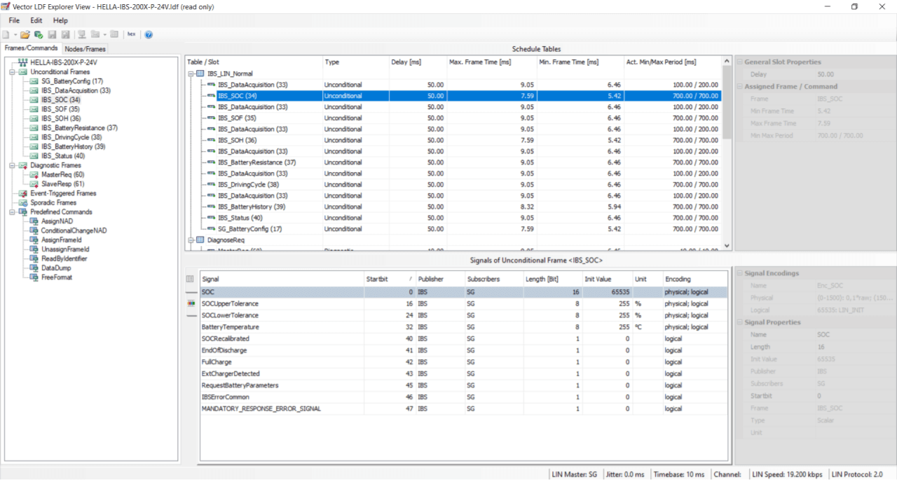 LDF Explorer lets you view and diagnose LDFs, useful in development
 The canmatrix Python library lets you automate your LDF-to-DBC
conversion
The canmatrix Python library lets you automate your LDF-to-DBC
conversion
 asammdf is great for ad hoc LIN data exploration and LDF decoding
 Grafana dashboards can be used to visualize decoded LIN data
How to convert an LDF to a DBC file
If you need to log and decode LIN bus data, you will need the LIN description file and a suitable data processing software tool.
A popular tool for LIN data logging is the CANedge, which can act as both a LIN slave (for silent monitoring) or a LIN master (to control the communication in a LIN cluster or e.g. collect data from isolated LIN nodes).
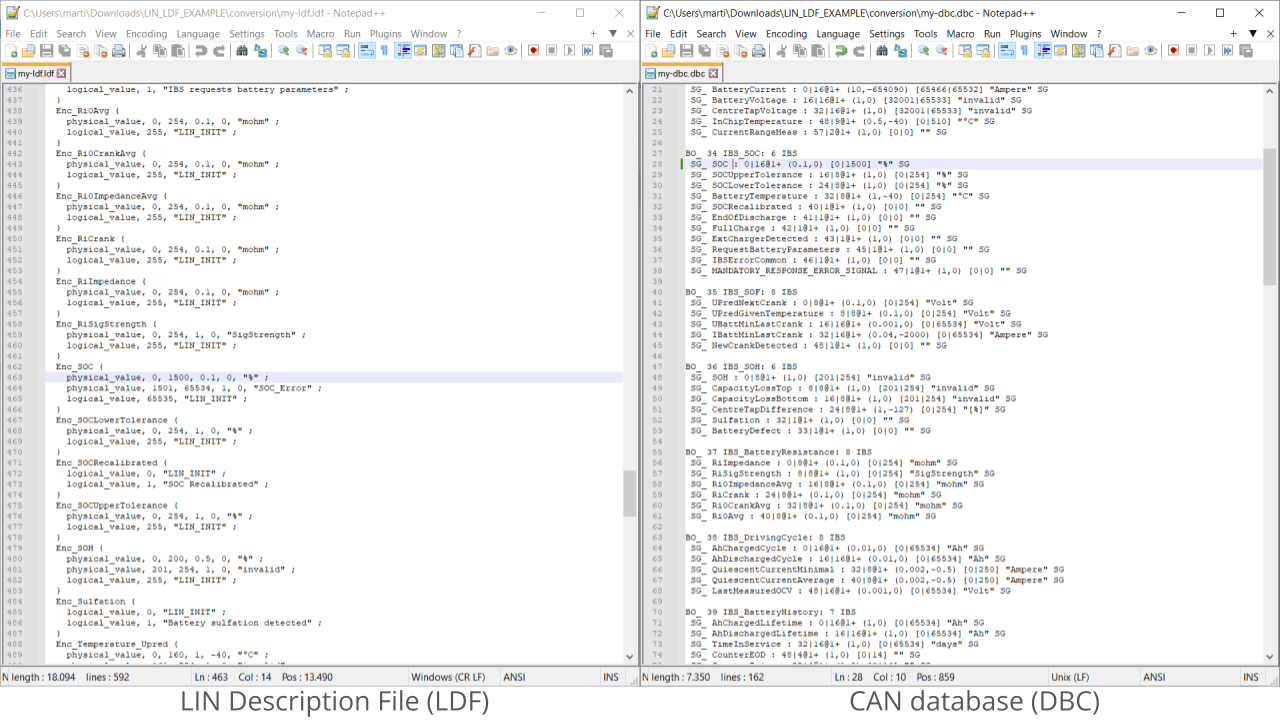
As shown above, you can load your raw LIN data in tools that natively support LDF files such as the asammdf GUI. However, some software tools only support DBC files for decoding the LIN data. We therefore focus this section on the link between LDF and DBC files, as well as how to convert your LDF into the DBC file format.

The process of decoding raw LIN bus data is similar to CAN bus decoding and requires the same information:
- ID: Which LIN frame ID contains the LIN signal
- Message name: The LIN message frame name
- Signal name: The LIN signal name
- Start bit: Start position of the LIN signal in the payload
- Length: Length of the LIN bus signal
- Endianness: The byte order (by default Intel for LIN)
- Scale: How to multiply the decimal value of the LIN signal bits
- Offset: By what constant should the LIN signal value be offset
- Unit/Min/Max: Additional supporting information (optional)
Below we provide two examples that show how this information can be found in the LDF - and how it can be added into a DBC.
Example 1: Convert BatteryVoltage
To show how the mapping between LDF and DBC files work, let us take the signal BatteryVoltage from the previous example LDF and convert it into a DBC file format.
To do so, we need to identify the details listed before from the LDF. As per the syntax section, the Frames section will provide us with the message name, data length and ID, as well as the signal name, signal bit start and signal bit length. Note that the signal bit length is provided 'indirectly' through the bit start of the next signal, so it is useful to note that it is also more explicitly available in the Signals section.
The Signal_encoding_types section will provide us with the scale, offset values, as well as the min/max values (in raw form).
For simplicity, we only consider the first physical_value entry of the signal. For this signal, this is an acceptable simplification because the second physical_value entry is 'invalid', while the logical_value entries similarly represent errors and initial values. In other words, for the purpose of providing a time series visualization of BatteryVoltage, these sections are not critical.
As displayed in the LDF vs. DBC comparison, we can create a full DBC entry for BatteryVoltage based on this information.


Example 2: Convert BatteryCurrent
Converting an LDF to a DBC file gets more complicated when there are multiple valid physical_value entries. A good example of this is the signal BatteryCurrent. This signal belongs to the same LIN message as BatteryVoltage, but it lists 7 physical_value entries that are all valid and thus necessary for properly decoding the LIN signal. The use of multiple ranges is powerful as it allows for a very high resolution (with a scale factor of 0.001) in the most relevant range of -20 A to +19.999 A, while still enabling decoding of more extreme ranges.
The simplest solution is to only map the most relevant range for our analysis, which would be similar to the BatteryVoltage process.
However, if you need to incorporate all of the ranges, an option is to use extended multiplexing in the DBC. This lets you define a signal to act as a multiplexor where the raw value of this signal determines how another signal is decoded. In our case, we can define a multiplexor 'BatCM' with the BatteryCurrent bit start and length. In turn, this lets us define a multiplexed signals for each physical_value entry in the LDF, which we can name e.g. BatC1, ..., BatC7. In the DBC, we specify that BatC1 uses the scale 10 and offset -1230 and that it is conditional on the multiplexor BatCM being equal to the range 1 to 66. We then continue this process for each relevant physical_value entry.
The end result is that we can effectively use DBC files for decoding LIN signals even when they use multiple valid physical_value sections, with the detail that the 'final signal' is stitched together by multiple individual signals.
To construct extended multiplexing DBC files, we recommend using Kvaser's database editor. This is a free tool, where you can enable extended multiplexing in the editor settings. In turn, this lets you directly toggle signals to be multiplexors, as well as define the raw value ranges within the editor.
canmatrix: Automate LDF to DBC
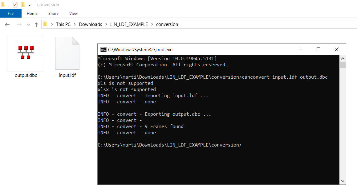
Converting an entire LDF to DBC can be cumbersome and time consuming. Luckily, 90%+ of the effort can be easily automated using an open source Python library called canmatrix.
Simply install Python, open your command line and run below:
pip install ldfparser
You can now convert an LDF to DBC via your command line:
To edit and validate your DBC file, we recommend to use a DBC file editor - our intro to DBC files list a number of free DBC editors for this purpose.
The resulting DBC file will incorporate 1:1 the frames and signals from your LDF, although it has the
Need to log LIN bus data?
Get your CAN/LIN logger today!


