OBD2 Explained - A Simple Intro [2026]
Need a simple, practical intro to OBD2?
In this guide we introduce the On Board Diagnostic (OBD2) protocol incl. the OBD2 connector, OBD2 parameter IDs (PID) and the link to CAN bus.
Note: This is a practical intro so you will also learn how to request and decode OBD2 data, key logging use cases and practical tips.
Learn below why this has become the #1 OBD2 tutorial.
You can also watch our OBD2 intro video above - or get the PDF
In this article

What is OBD2?
OBD2 is your vehicle's built-in self-diagnostic system. It is a standardized protocol that allows extraction of diagnostic trouble codes (DTCs) and real-time data via the OBD2 connector.
You've probably encountered OBD2 already:
Ever noticed the malfunction indicator light on your dashboard?
That is your car telling you there is an issue. If you visit a mechanic, he will use an OBD2 scanner to diagnose the issue.
To do so, he will connect the OBD2 reader to the OBD2 16 pin connector near the steering wheel. The tool sends 'OBD2 requests' to the car and the car responds with 'OBD2 responses' that can contain e.g. speed, fuel level or Diagnostic Trouble Codes (DTCs) - making it possible to troubleshoot issues faster.

Does my car support OBD2?
In short: Probably!
Almost all newer non-electric cars support OBD2 and most run on CAN bus. For older cars, note that even if a 16 pin OBD2 connector is present, it may still not support OBD2. One way to determine compliance is to see where & when it was bought new:
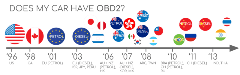
OBD2 history
OBD2 originates from California where the California Air Resources Board (CARB) required OBD in all new cars from 1991+ for emission control purposes.
The OBD2 standard was recommended by the Society of Automotive Engineers (SAE) and standardized DTCs and the OBD connector across manufacturers (SAE J1962).
From there, the OBD2 standard was rolled out step-by-step:
- 1996: OBD2 made mandatory in USA for cars/light trucks
- 2001: Required in EU for gasoline cars
- 2003: Required in EU also for diesel cars (EOBD)
- 2005: OBD2 was required in US for medium duty vehicles
- 2008: US cars must use ISO 15765-4 (CAN) as OBD2 basis
- 2010: Finally, OBD2 was required in US heavy duty vehicles


OBD2 future
OBD2 is here to stay - but in what form?
Below we highlight important trends:
Legislated OBD2 has originally been designed for the purpose of emissions control/testing. As an implication, electric vehicles are not required to support OBD2 in any shape or form. This can be seen in practice from the fact that almost none of the modern EVs support any of the standard OBD2 requests. Instead, most of them utilize OEM-specific UDS communication. Generally, this makes it impossible to decode data from these electric vehicles, except for cases where the decoding rules have been reverse engineered - see e.g. our case studies for electric cars incl. Tesla, Hyundai/Kia, Nissan and VW/Skoda EVs.
OBD2 is today implemented in a variety of ways and has limitations in regards to e.g. data richness and lower-layer protocols. In response to this, modern alternatives have been developed including WWH-OBD (World Wide Harmonized OBD) and OBDonUDS (OBD on UDS). Both seek to streamline and enhance OBD communication by leveraging the UDS protocol as basis. To learn more about these protocols, see our intro to UDS.
In today's world of connected cars, OBD2 tests can seem cumbersome: Manually doing emission control checks is time-consuming and expensive.
The solution? OBD3 - adding telematics to all cars.
Basically, OBD3 adds a small radio transponder (as in e.g. bridge tolls) to all cars. Using this, the car vehicle identification number (VIN) and DTCs can be sent via WiFi to a central server for checks.
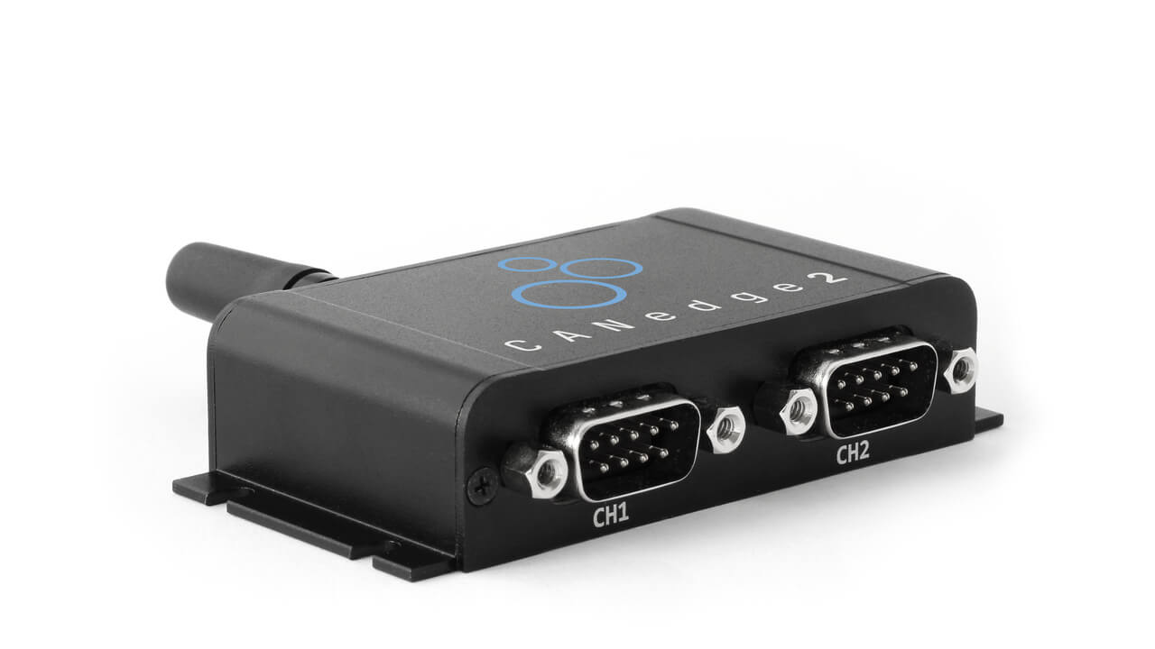
Many devices today already facilitate transfer of CAN or OBD2 data via WiFi/cellular - e.g. the CANedge2 WiFi CAN logger or the CANedge3 3G/4G CAN logger.
This saves cost and is convenient, but it is also politically a challenge due to surveillance concerns.
The OBD2 protocol was originally designed for stationary emission controls.
Yet, today OBD2 is used extensively for generating real-time data by 3rd parties - via OBD2 dongles, CAN loggers etc. However, the German car industry is looking to change this:
OBD has been designed to service cars in repair shops. In no way has it been intended to allow third parties to build a form of data-driven economy on the access through this interface"
- Christoph Grote, SVP Electronics, BMW (2017)
The proposal is to "turn off" the OBD2 functionality while driving - and instead collect the data in a central server. This would effectively put the manufacturers in control of the 'automotive big data'.
The argumentation is based in security (e.g. removing the risk of car hacking), though many see it as a commercial move. Whether this becomes a real trend is to be seen - but it may truly disrupt the market for OBD2 3rd party services.

OBD2 standards
On board diagnostics, OBD2, is a higher layer protocol (like a language). CAN is a method for communication (like a phone). This makes OBD2 comparable to other CAN based higher-layer protocols like J1939, CANopen and NMEA 2000.
In particular, the OBD2 standards specify the OBD2 connector, lower-layer protocols, OBD2 parameter IDs (PID) and more.
The standards can be displayed in a 7-layer OSI model - and in the next sections we focus on the most important ones.
In the OSI model overview, you may note that several layers are covered by both SAE and ISO standards. Generally, this reflects standards for OBD defined in USA (SAE) and EU (ISO). Several standards are almost technically equivalent, for example SAE J1979 vs. ISO 15031-5 and SAE J1962 vs. ISO 15031-3.


The OBD2 connector [SAE J1962]
The 16-pin OBD2 connector lets you access data from your car easily and is specified in the standard SAE J1962 / ISO 15031-3.
In the illustration is an example of a Type A OBD2 pin connector (also sometimes referred to as the Data Link Connector, DLC).
A few things to note:
- The connector is near your steering wheel, but may be hidden
- Pin 16 supplies battery power (often while the ignition is off)
- The OBD2 pinout depends on the communication protocol
- The most common lower-layer protocol is CAN bus, meaning that pins 6 (CAN-H) and 14 (CAN-L) will typically be connected
OBD2 connector - type A vs. B
In practice, you may encounter both the type A and type B OBD2 connector. Typically, type A will be found in cars, while type B is common in medium and heavy duty vehicles.
As evident from the illustration, the two types share similar OBD2 pinouts, but provide two different power supply outputs (12V for type A and 24V for type B). Often the baud rate will differ as well, with cars typically using 500K, while most heavy duty vehicles use 250K (more recently with support for 500K).
To help physically distinguish between the two types of OBD2 sockets, note that the type B OBD2 connector has an interrupted groove in the middle. As a result, a type B OBD2 adapter cable will be compatible with both types A and B, while a type A will not fit into a type B socket.


OBD2 and CAN bus [ISO 15765-4]
Since 2008, CAN bus has been the mandatory lower-layer protocol for OBD2 in all cars sold in the US as per ISO 15765.
ISO 15765-4 (aka Diagnostics over CAN or DoCAN) refers to a set of restrictions applied to the CAN standard (ISO 11898).
Specifically, it standardizes the CAN interface for test equipment with focus on the physical, data link and network layer:
- The CAN bus bit-rate must be either 250K or 500K
- The CAN IDs can be 11-bit or 29-bit
- Specific CAN IDs are used for OBD requests/responses
- The diagnostic CAN frame data length must be 8 bytes
- The OBD2 adapter cable must be max 5 meters
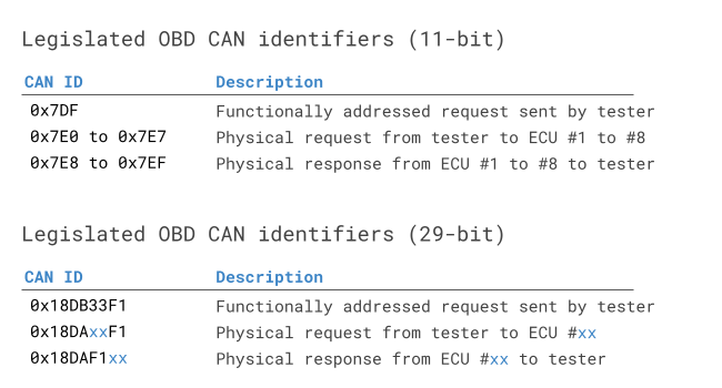
OBD2 CAN identifiers (11-bit, 29-bit)
All OBD2 communication involves request / response messages.
In most cars, 11-bit CAN IDs are used for OBD2 communication. Here, the 'Functional Addressing' ID is 0x7DF, which corresponds to asking all OBD2 compatible ECUs if they have data to report on the requested parameter (see ISO 15765-4). In contrast, CAN IDs 0x7E0-0x7E7 can be used to perform 'Physical Addressing' requests from specific ECUs (less commonly used).
ECUs can respond with 11-bit IDs 0x7E8-0x7EF. The most common response ID is 0x7E8 (ECM, Engine Control Module) and to some extent 0x7E9 (TCM, Transmission Control Module).
In some vehicles (e.g. vans and light/medium/heavy duty vehicles), you may find that OBD2 communication uses extended 29-bit CAN identifiers instead of 11-bit CAN identifiers.
Here, the 'Functional Addressing' CAN ID is 0x18DB33F1.
If the vehicle responds, you will see responses with CAN IDs 0x18DAF100 to 0x18DAF1FF (typically 18DAF110 and 18DAF11E). The response ID is also sometimes shown in the 'J1939 PGN' form, specifically the PGN 0xDA00 (55808), which in the J1939-71 standard is marked as 'Reserved for ISO 15765-2'.


OBD2 vs. proprietary CAN protocols
Importantly, your car's electronic control units (ECUs) do not rely on OBD2 to function. Rather, each original equipment manufacturer (OEM) implements their own proprietary CAN protocols for this purpose. These CAN protocols may be specific to the vehicle brand, model and year. If you are not the OEM, you will normally not be able to interpret this data (unless you can reverse engineer it). See our AI CAN sniffer guide.
If you connect a CAN bus data logger to your car's OBD2 connector, you may see the OEM-specific CAN data, typically broadcast at a rate of 1000-2000 frames/second. However, in many newer cars a 'gateway' blocks access to this CAN data and only enables OBD2 communication via the OBD2 connector.
In short, think of OBD2 as an 'extra' higher-layer protocol in parallel to the OEM-specific protocol.
Bit-rate and ID validation
As explained, OBD2 may use one of two bit-rates (250K, 500K) and one of two CAN ID lengths (11-bit, 29-bit). This results in 4 potential combinations. In modern cars, 500K and 11-bit IDs is the most common one - but external tools should verify this in a systematic way.
ISO 15765-4 provides recommendations for how to perform a systematic initialization sequence to determine the relevant combination, which we illustrate in the flowchart. The method leverages that OBD2 compliant vehicles must respond to a specific mandatory OBD2 request (see the OBD2 PID section for details) - and the fact that transmitting data with an incorrect bit-rate will cause CAN error frames.
Newer versions of ISO 15765-4 take into account that vehicles may support OBD communication via OBDonUDS rather than OBDonEDS. Most of this article focuses on OBD2/OBDonEDS (OBD on emission diagnostic service as per ISO 15031-5/SAE J1979) as opposed to WWH-OBD/OBDonUDS (OBD on Unified Diagnostic Service as per ISO 14229, ISO 27145-3/SAE J1979-2).
To test for the 'protocol' of OBDonEDS vs OBDonUDS, a test tool may add additional request messages, specifically sending UDS requests with 11-bit/29-bit functional address IDs for service 0x22 and data identifier (DID) 0xF810 (protocol identification). Vehicles that support OBDonUDS must have ECUs that reply to this DID.
In practice, OBDonEDS (aka OBD2, SAE OBD, EOBD or ISO OBD) is used in most non-EV cars today, while WWH-OBD is primarily used in EU trucks/buses.


Five lower-layer OBD2 protocols
CAN today serves as the lower-layer basis for OBD2 in the vast majority of cars as per ISO 15765.
However, if you inspect an older car (pre 2008), it is useful to know the other four lower-layer protocols that have been used as basis for OBD2. Note also the pinouts, which can be used to determine which protocol may be used in your car.
- ISO 15765 (CAN bus): Mandatory in US cars since 2008 and is today used in the vast majority of cars
- ISO14230-4 (KWP2000): The Keyword Protocol 2000 was a common protocol for 2003+ cars in e.g. Asia
- ISO 9141-2: Used in EU, Chrysler & Asian cars in 2000-04
- SAE J1850 (VPW): Used mostly in older GM cars
- SAE J1850 (PWM): Used mostly in older Ford cars
Transporting OBD2 messages via ISO-TP [ISO 15765-2]
All OBD2 data is communicated on the CAN bus through a transport protocol called ISO-TP (ISO 15765-2). This enables communication of payloads that exceed 8 bytes. This is necessary in OBD2 e.g. when extracting the Vehicle Identification Number (VIN) or Diagnostic Trouble Codes (DTCs). Here, ISO 15765-2 enables segmentation, flow control and reassembly. For details, see our intro to UDS.
Often, however, the OBD2 data will fit in a single CAN frame. Here, ISO 15765-2 specifies the use of a 'Single Frame' (SF), implying that the 1st data byte (aka PCI field) contains the payload length (excluding padding), leaving 7 bytes for the OBD2 related communication.

The OBD2 diagnostic message [SAE J1979, ISO 15031-5]
To better understand OBD2 on CAN, let us consider a raw 'Single Frame' OBD2 CAN message. In simplified terms, an OBD2 message is comprised of an identifier, data length (PCI field) and data. The data is split in Mode, parameter ID (PID) and data bytes.

Example: OBD2 request/response
Before we cover each part of the OBD2 message, consider this example request/response for the parameter 'Vehicle Speed'.
Here, an external tool sends a request message to the car with CAN ID 0x7DF and 2 payload bytes: Mode 0x01 and PID 0x0D. The car responds via CAN ID 0x7E8 and 3 payload bytes, including the value of Vehicle Speed in the 4th byte, 0x32 (50 in decimal form).
By looking up the decoding rules for OBD2 PID 0x0D we determine that the physical value is 50 km/h.
Next, we will focus on the OBD2 modes and PIDs.


The 10 OBD2 services (aka modes)
There are 10 OBD2 diagnostic services (or modes). Mode 0x01 shows current real-time data, while others are used to show/clear diagnostic trouble codes (DTCs) or show freeze frame data.
Vehicles do not have to support all OBD2 modes - and they may support modes outside the 10 standardized modes (aka OEM-specific OBD2 modes).
In OBD2 messages, the mode is in the 2nd byte. In the request, the mode is included directly (e.g. 0x01), while in the response 0x40 is added to the mode (e.g. resulting in 0x41).
OBD2 parameter IDs (PID)
Each OBD2 mode contains parameter IDs (PIDs).
As an example, mode 0x01 contains ~200 standardized PIDs with real-time data on e.g. speed, RPM and fuel level. However, a vehicle does not have to support all OBD2 PIDs in a mode. In practice, most vehicles only support a small subset.
In this regard, one PID is special.
Specifically, if an emissions-related ECU supports any OBD2 services, then it must support mode 0x01 PID 0x00. In response to this PID, the vehicle ECU informs whether it supports PIDs 0x01-0x20. This makes PID 0x00 useful as a fundamental 'OBD2 compatibility test'. Further, PIDs 0x20, 0x40, ..., 0xC0 can be used to determine the support for the remaining mode 0x01 PIDs.

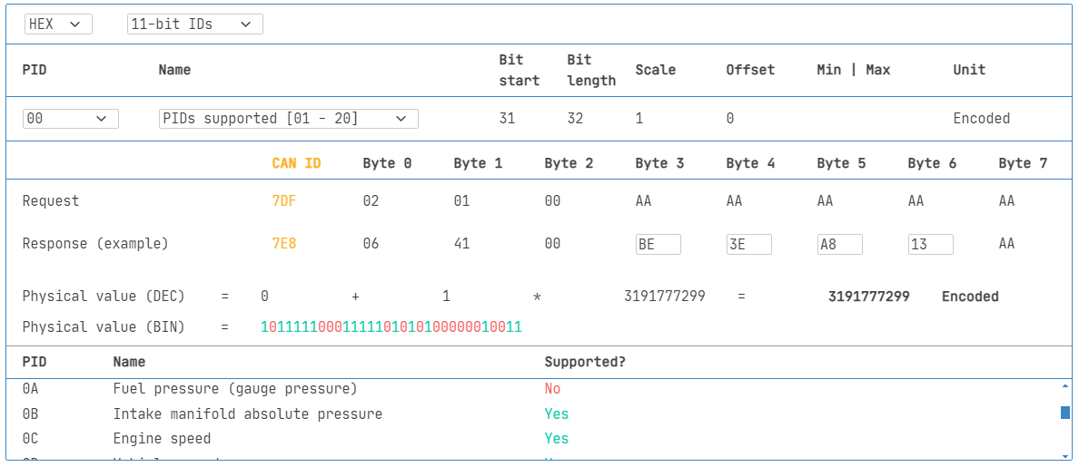
Tip: OBD2 PID overview tool
In the appendices of SAE J1979 and ISO 15031-5 you will find scaling info for standard OBD2 PIDs, which allows you to decode the data into physical values (as explained in our CAN bus intro).
If you need to look up a mode 0x01 PID, check out our OBD2 PID overview tool. This helps you construct OBD2 request frames and dynamically decode the OBD2 responses.
OBD2 PID overview toolHow to log and decode OBD2 data
In this section we provide a practical example of how you can log OBD2 data with the CANedge CAN bus data logger.
The CANedge lets you configure custom CAN frames to be transmitted which allows it to be used for e.g. OBD2 logging.
Once configured, the device can be easily connected to your vehicle via our OBD2-DB9 adapter cable.


You can send a CAN frame at e.g. 500K, then check if it is successfully sent
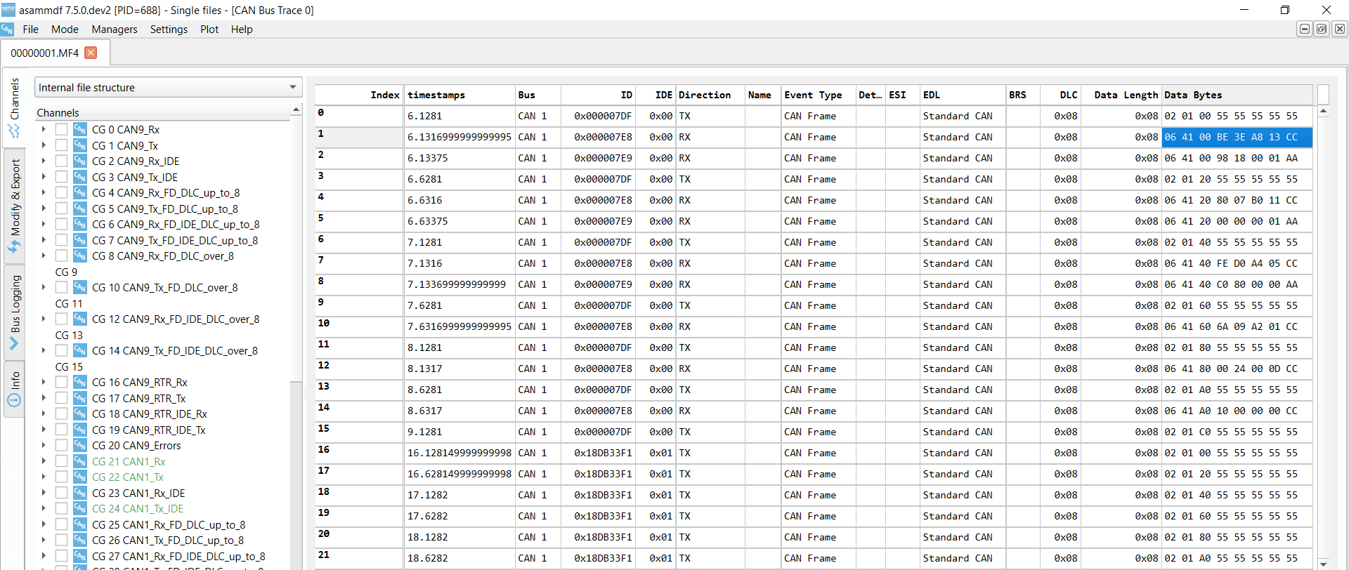
The responses to 'Supported PIDs' can be reviewed in asammdf
'Supported PIDs' results can be decoded via our OBD2 PID lookup tool
#1: Test bit-rate, IDs & supported PIDs
As discussed, ISO 15765-4 describes how to determine which bit-rate and IDs are used by a specific vehicle. You can test this with the CANedge as below (see the CANedge Intro for details):
- Send CAN frame at 500K and check if succesful (else try 250K)
- Use the identified bit-rate for subsequent communication
- Send multiple 'Supported PIDs' requests and review the results
- Based on response IDs you can determine 11-bit vs. 29-bit
- Based on response data you can see what PIDs are supported
We provide plug & play configs to perform the above tests.
Most 2008+ non-EV cars support 40-80 PIDs via 500K bit-rate, 11-bit CAN IDs and the OBD2/OBDonEDS protocol.
As exemplified in the asammdf GUI screenshot, it is common to see multiple responses to a single OBD request. This is because we use the 0x7DF request ID, which polls all ECUs for a response. Since all OBD2/OBDonEDS-compliant ECUs must support service 0x01 PID 0x00, there are often many responses to this PID in particular. As evident, for subsequent 'Supported PIDs' requests there are gradually fewer ECUs that respond. Note also that the ECM ECU (0x7E8) itself supports all the PIDs that are supported by other ECUs in this example, meaning the busload may be reduced by only asking specifically this ECU for responses by changing to the 'Physical Addressing' CAN ID 0x7E0 for subsequent communication.
#2: Configure OBD2 PID requests
You now know which OBD2 PIDs are supported by your vehicle - and what bit-rate and CAN IDs to use when requesting them.
Next, you configure your transmit list with PIDs of interest.
A few things to consider:
- CAN IDs: Shift to 'Physical Addressing' request IDs (e.g. 0x7E0) to avoid multiple responses to each request
- Spacing: Add 300-500 ms between each OBD2 request (spamming the ECUs may cause them to not respond)
- Battery drain: Use triggers to stop transmitting when the vehicle is inactive (to avoid 'waking up' ECUs)
- Filters: Add filters to only record OBD2 responses (e.g. if your vehicle also outputs OEM-specific CAN data)
Note: The CANedge config editor has a built-in OBD2 tool for quickly constructing your transmit list.
Once configured, the device is ready to log raw OBD2 data!
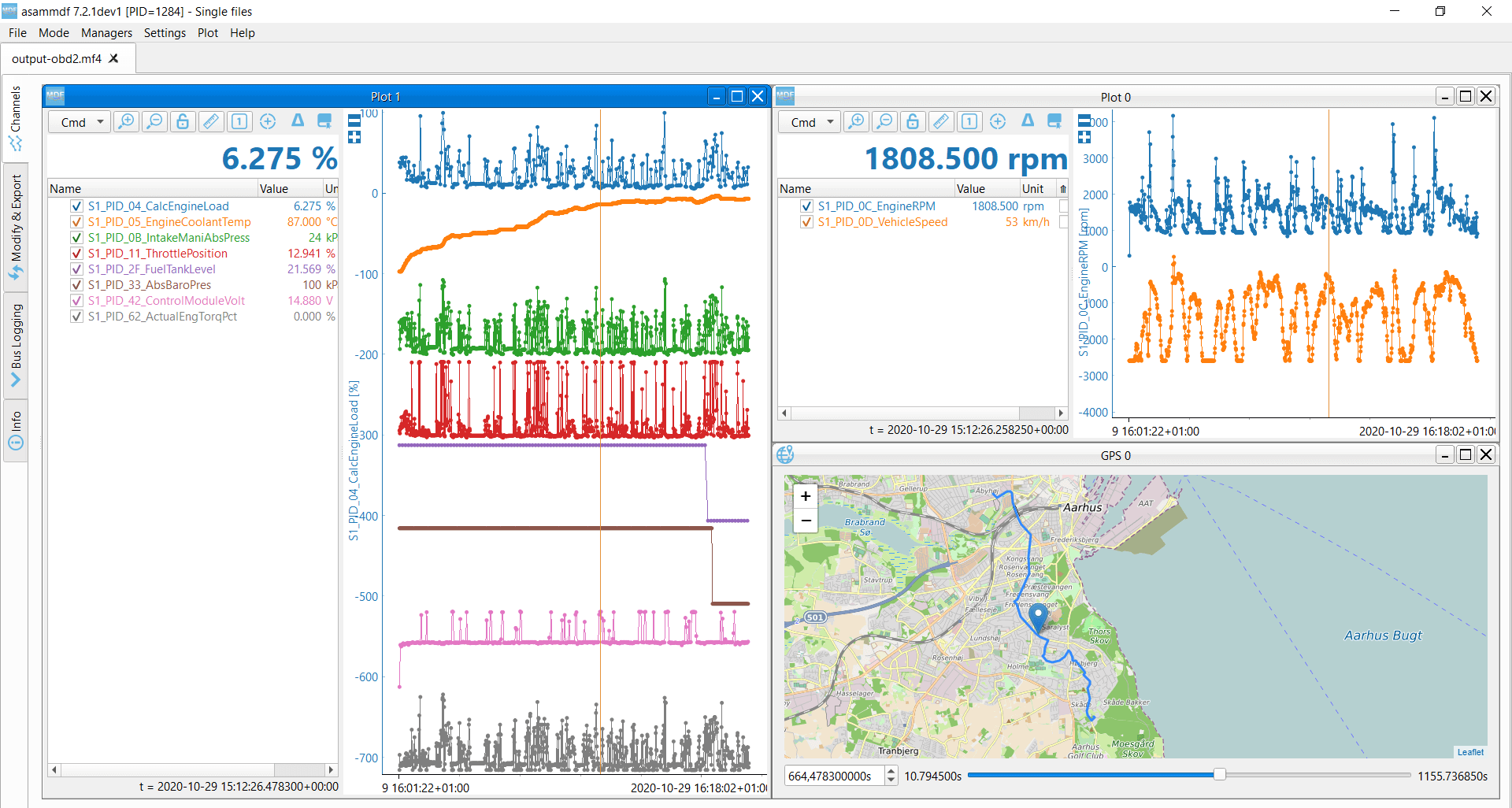
asammdf lets you DBC decode and visualize OBD2 data
#3: DBC decode raw OBD2 data
Finally, to analyze/visualize your data, you need to decode the raw OBD2 data into 'physical values' (like km/h or degC).
The necessary decoding information can be found in ISO 15031-5/SAE J1979 (and e.g. on Wikipedia). For convenience we provide a free OBD2 DBC file that makes it easy to DBC decode raw OBD2 data in most CAN bus software tools.
Note that decoding OBD2 data is a bit more complex than regular CAN signals. This is because different OBD2 PIDs are transported using the same CAN ID (e.g. 0x7E8). As such, the CAN ID is not sufficient to uniquely identify what signals are encoded in the payload.
To solve this, one must leverage both the CAN ID, OBD2 mode and OBD2 PID to identify the signal. This is a form of multiplexing referred to as 'extended multiplexing', which can be implemented in e.g. DBC files.
CANedge: OBD2 data logger
The CANedge lets you easily record OBD2 data to an 8-32 GB SD card. Simply connect it to e.g. a car/truck to start logging - and decode the data via free software/APIs and our OBD2 DBC.
OBD2 logger intro CANedgeHow to stream & decode OBD2 data
You can also stream OBD2 data in real-time via a CANsub.2/CANsub.4 interface and our free webCAN software. The concepts are largely the same as for the CANedge, but a few things differ slightly when streaming.
First, you can rapidly test if webCAN's bit-rate auto-detection identifies the correct rate for your vehicle - and if not, simply switch to a fixed bit-rate (e.g. 500K) and retry.
Next, you can quickly set up custom transmit lists for requesting OBD2 data via webCAN's 'DBC encoder' option - letting you construct OBD2 requests directly from our OBD2 DBC file by selecting PIDs by name rather than crafting the raw payloads.
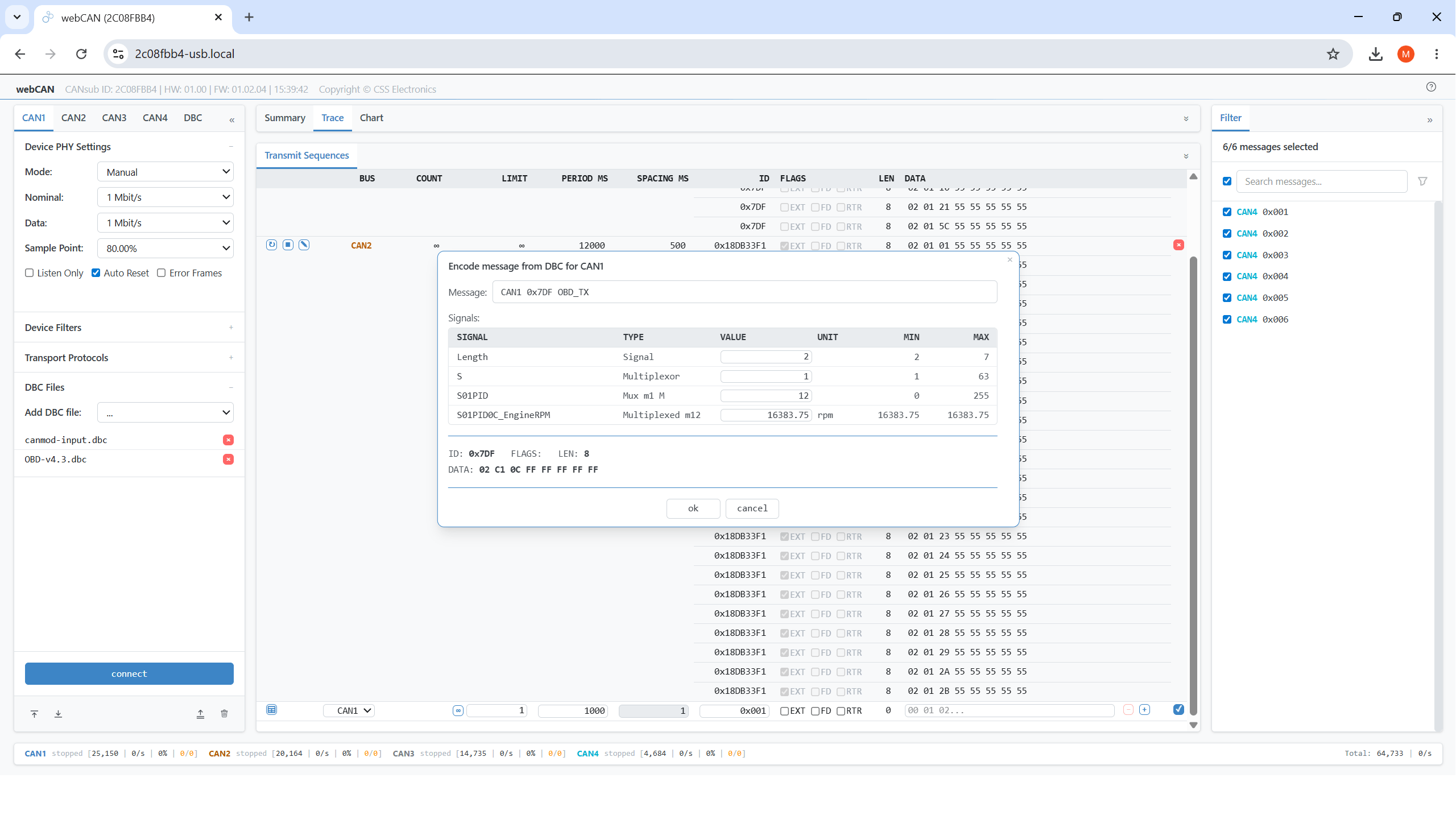
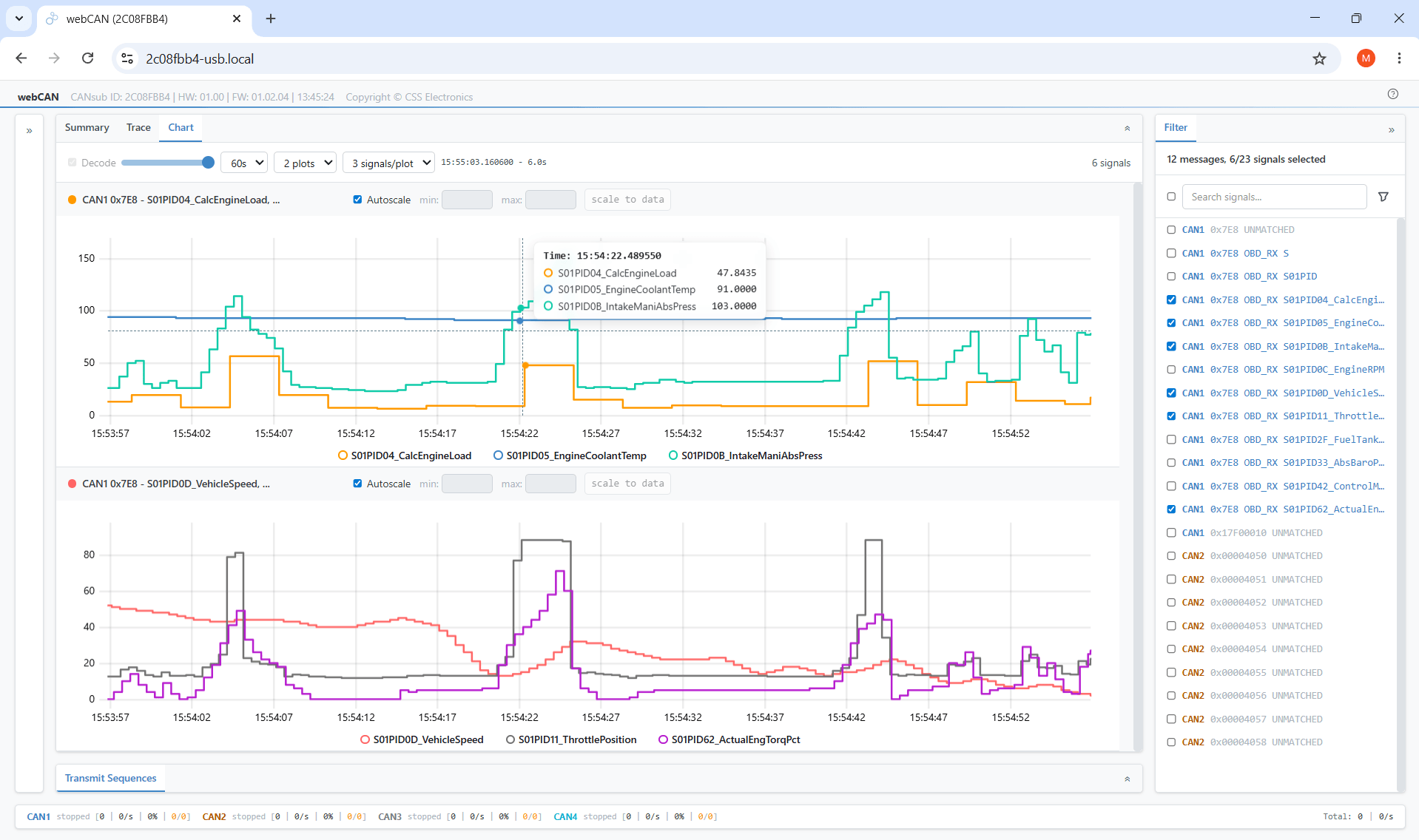
The streamed OBD2 data can be easily DBC decoded via our OBD2 DBC for live real-time signal plots in webCAN - including support for the ISO TP transport protocol (as outlined below) for handling multi-frame OBD2 responses.
As with the CANedge, the CABsub's multi-CAN support lets you easily add additional CAN data - e.g. from a GPS-to-CAN or temperature-to-CAN module to enrich your OBD2 data.
CANsub: OBD2-USB interface
The CANsub.2/CANsub.4 lets you stream OBD2 data in real-time via USB or Ethernet - viewing raw/decoded OBD2 PIDs directly in your browser via webCAN with zero software installation.
Buy now webCAN software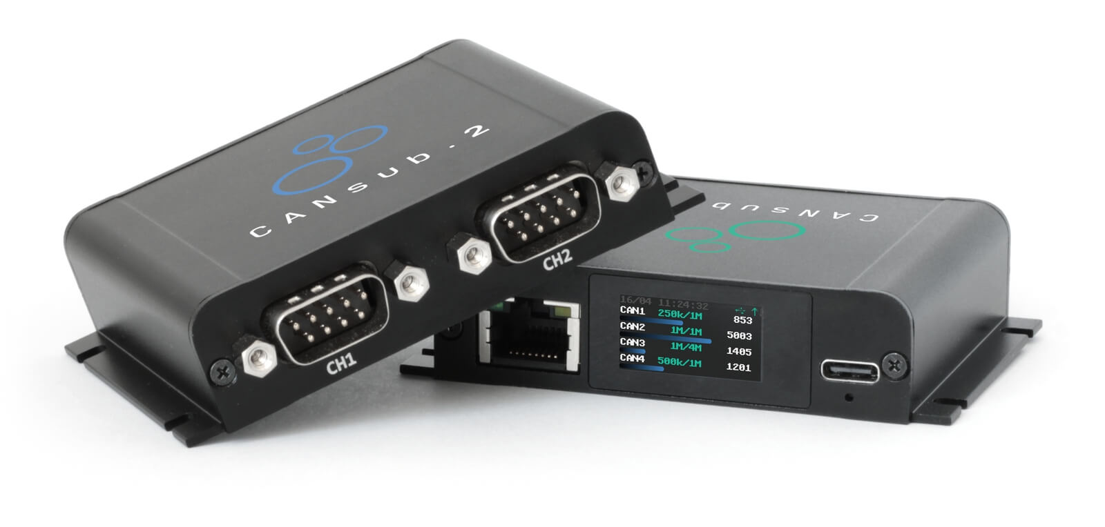
OBD2 multi-frame examples [ISO-TP]
All OBD2 data is communicated using the ISO-TP (transport protocol) as per ISO 15765-2. Most of the examples so far reflect single-frame communication. In this section, we provide some examples of multi-frame communication.
Multi-frame OBD2 communication requires flow control frames (see our UDS intro). In practice, this can be done by transmitting a static flow control frame e.g. 50 ms after the initial request frame, as per the CANedge configuration example shown.
Further, multi-frame OBD2 responses require CAN software/API tools that support ISO-TP, like the CANedge MF4 decoders.

Example 1: OBD2 Vehicle Identification Number (VIN)
The Vehicle Identification Number (VIN) is often relevant to telematics, diagnostics and more (see our intro to UDS for details). To extract the Vehicle Identification Number from a vehicle using OBD2 requests, you use mode 0x09 and PID 0x02:
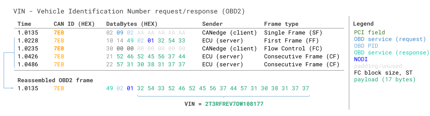
The tester tool sends a Single Frame request with the PCI field (0x02), request service identifier (0x09) and PID (0x02).
The vehicle responds with a First Frame containing the PCI, length (0x014 = 20 bytes), mode (0x49, i.e. 0x09 + 0x40) and PID (0x02). Following the PID is the byte 0x01 which is the Number Of Data Items (NODI), in this case 1 (see ISO 15031-5 / SAE J1979 for details). The remaining 17 bytes equal the VIN and can be translated from HEX to ASC via methods discussed in our intro to UDS.
Example 2: OBD2 multi-PID request (6x)
External tools are allowed to request up to 6 mode 0x01 OBD2 PIDs in a single request frame. The ECU shall respond with data for supported PIDs (with unsupported PIDs left out of the response), if necessary across multiple frames as per ISO-TP.
This is a powerful feature that lets you collect OBD2 data at higher frequency and efficiency, though it also implies that the signal encoding is specific to your request method, making e.g. the use of generic OBD2 DBC files difficult for such use cases. We do not recommend using this method in practice. Below we provide an example trace of what this may look like:
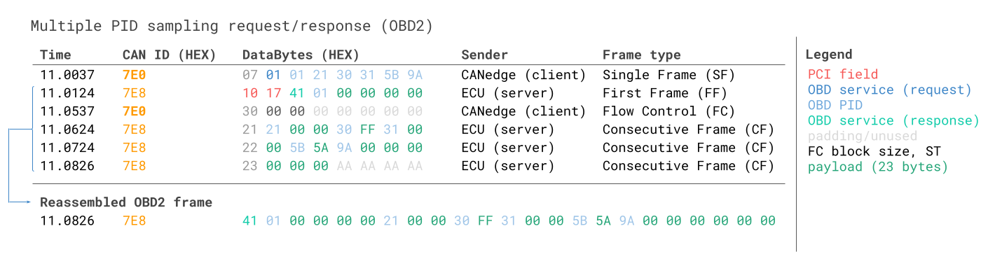
The multi-frame response is similar to the VIN example, though with the twist that the payload includes the requested PIDs as well as the data for each of them. Note that the PIDs in the example are ordered similarly to how they are requested, which is common in practice (but not strictly required by the ISO 15031-5 standard).
Decoding this response via e.g. DBC files is very difficult in practice and hence we would not recommend to use this approach for practical data logging, unless you are working with a tool that has built-in support specifically for this. Effectively, you will be working with a case of extended multiplexing, but with multiple cases of this throughout the payload - with the added challenge that your DBC file would need to account for the specific payload position of each PID, which makes it very difficult to generalize the DBC across vehicles that may differ in supported PIDs. Further, this becomes very difficult/impossible to handle via pure DBC manipulations if you are sending several such multi-PID requests, as you will then lack a method for uniquely identifying these messages from eachother.
This could be worked around through e.g. a custom script and by recording also the transmit messages from your testing tool, in which case the script could incorporate a logic of interpreting the response message in combination with the request message - but generally such approaches are difficult to handle at scale.
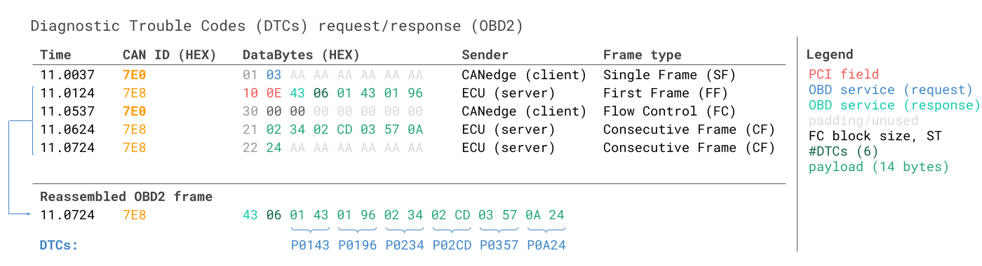
Example 3: OBD2 Diagnostic Trouble Codes (DTCs)
You can use OBD2 to request emissions-related Diagnostic Trouble Codes (DTCs) from using mode 0x03, i.e. 'Show stored Diagnostic Trouble Codes'. No PID is included in the request. The targeted ECU(s) will then respond with the number of DTCs they have stored (including potentially 0 if they have none), with each DTC taking up 2 data bytes. As a result, multi-frame responses are necessary when more than 2 DTCs are stored.
The 2-byte DTC value is typically split into two parts, as per ISO 15031-5/ISO 15031-6. The first 2 bits define the 'category', while the remaining 14 bits define a 4-digit code (displayed in hexadecimal), as per the visual. The decoded DTC values can be looked up in various OBD2 DTC lookup tools like repairpal.com.
Below example shows a request to an ECU with 6 DTCs stored.

OBD2 data logging - use case examples
OBD2 data from cars and light trucks can be used in various use cases:

Logging data from cars/trucks
OBD2 data from cars/trucks can e.g. be used to reduce fuel costs, improve driving, test prototype parts and insurance
obd2 logger
Real-time car diagnostics
OBD2 interfaces can be used to stream human-readable OBD2 data in real-time, e.g. for diagnosing vehicle issues
obd2 streaming
Vehicle predictive maintenance
Cars and light trucks can be monitored via IoT OBD2 loggers in the cloud to predict and avoid breakdowns
predictive maintenance
Automotive blackbox logger
An OBD2 logger can serve as a 'blackbox' for vehicles or equipment, providing data for e.g. disputes or diagnostics
can bus blackboxDo you have an OBD2 data logging/streaming use case? Reach out for free sparring!
Contact usFor more intros, see our guides section - or download the 'Ultimate Guide' PDF.
Need to log/stream OBD2 data?
Get your OBD2 data logger/interface today!