CAN FD Explained - A Simple Intro [2026]
Need a simple, practical intro to CAN FD?
In this guide we introduce CAN FD (CAN Flexible Data-rate) - incl. CAN FD frames, overhead & efficiency, example applications and logging use cases.
Note: CAN FD can seem complex - so this tutorial is a visual intro in layman's terms.
Read on below to fully understand CAN FD.
You can also watch our CAN FD intro video above - or get the PDF.
In this article

Why CAN FD?
The CAN protocol has been around since 1986 and it's popular: Practically any machine that moves utilizes CAN today - whether it's cars, trucks, boats, planes or robots.
But with the rise of modern technology, the "Classical" CAN protocol (official term used in ISO 11898-1:2015) is pressured:
- A rise in vehicle functionality is driving an explosion in data
- Networks are increasingly limited by the 1-Mbit/s bandwidth
- To cope, OEMs create complex & costly workarounds
Specifically, Classical CAN struggles with substantial overhead (>50%) as each CAN data frame can only contain 8 data bytes. Further, the network speed is limited to 1 Mbit/s, restricting the implementation of data-producing features.
CAN FD resolves these issues - making it future-proof.

What is CAN FD?
The CAN FD protocol was pre-developed by Bosch (with industry experts) and released in 2012. It was improved through standardization and is now in ISO 11898-1:2015. The original Bosch CAN FD version (non-ISO CAN FD) is incompatible with ISO CAN FD.
CAN FD offers four major benefits:
 #1 Increased length
CAN FD supports up to 64 data bytes per data frame vs. 8 data bytes for Classical CAN. This reduces the protocol overhead and leads to an improved protocol efficiency.
 #2 Increased speed
CAN FD supports dual bit rates: The nominal (arbitration) bit-rate limited to 1 Mbit/s as in Classical CAN - and the data bit-rate, which depends on the network topology/transceivers. In practice, data bit-rates up to 5 Mbit/s are achievable.
 #3 Better reliability
CAN FD uses an improved cyclic redundancy check (CRC) and the "protected stuff-bit counter", which lower the risk of undetected errors. This is e.g. vital in safety-critical applications like vehicles and industrial automation.
 #4 Smooth transition
CAN FD and Classical CAN only ECUs can be mixed under certain conditions. This allows for a gradual introduction of CAN FD nodes, greatly reducing costs and complexity for OEMs.
In practice, CAN FD can improve network bandwidth by 3-8x vs Classical CAN, creating a simple solution to the rise in data.
How does CAN FD work?
So CAN FD seems pretty simple: Speed up the data transmission and pack more data into each message, right?
In practice, however, it's not that straight forward. Below we outline the main challenges that the CAN FD solution had to solve.
Two key challenges
Before looking at the CAN FD data frame, it's key to understand two core parts of Classical CAN that we want to maintain:

#1 Avoid critical message delays
Why not simply pack Classical CAN frames with 64 bytes of data?
Doing so would reduce overhead and simplify message interpretation. However, if the bit-rate is unchanged, this would also block the CAN bus for longer, potentially delaying mission-critical higher-priority data frames.
#2 Maintain practical CAN wire lengths
So, more speed is needed to send more data per message.
But why not speed up the entire CAN message (rather than just the data phase)?
This is due to "arbitration": If 2+ nodes transmit data simultaneously, arbitration determines which node takes priority. The "winner" continues sending (without delay), while the other nodes "back off" during the data transmission.
During arbitration, a "bit time" provides sufficient delay between each bit to allow every node on the network to react. To be certain that every node is reached within the bit time, a CAN network running at 1 Mbit/s needs to have a maximum length of 40 meters (in practice 25 meters). Speeding up the arbitration process would reduce the maximum length to unsuitable levels.
On the other hand, after arbitration there's an "empty highway" - enabling high speed during the data transmission (when there is just one node driving the bus-lines). Before the ACK slot - when multiple nodes acknowledge the correct reception of the data frame - the speed needs to be reduced to the nominal bit-rate.
In short, it is necessary to find a way to only increase the speed during the data transmission.
Solution: The CAN FD frame
The CAN FD protocol introduces an adjusted CAN data frame to enable the extra data bytes and flexible bit-rates.
Below we compare an 11-bit Classical CAN frame vs. an 11-bit CAN FD frame (29-bit is also supported):
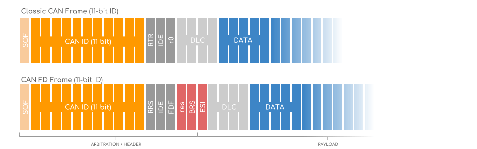
Below we go through the differences step-by-step:
RTR vs. RRS: The Remote Transmission Request (RTR) is used in Classical CAN to identify data frames and corresponding remote frames. In CAN FD, remote frames are not supported at all - the Remote Request Substitution (RRS) is always dominant (0).
r0 vs. FDF: In Classical CAN, r0 is reserved and dominant (0). In CAN FD, it's named FDF and recessive (1).
After the r0/FDF bit, the CAN FD protocol adds "3 new bits". Note that nodes that are not CAN FD capable produce an error frame after the FDF bit.
res: This new reserved bit plays the same role as r0 - i.e. it may in the future be set to recessive (1) to denote a new protocol.
BRS: The Bit Rate Switch (BRS) can be dominant (0), meaning that the CAN FD data frame is sent at the arbitration rate (i.e. up to max 1 Mbit/s). Setting it to recessive (1) means that the remaining part of the data frame is sent at a higher bit rate (up to 5 Mbit/s).
ESI: The Error Status Indicator (ESI) bit is by default dominant (0), i.e.'error active'. If the transmitter becomes 'error passive' it'll be recessive (1) to indicate it is in error passive mode.
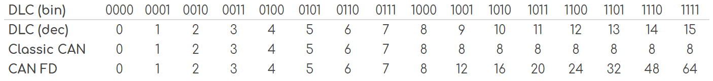
DLC: Like in Classical CAN, the CAN FD DLC is 4 bits and denotes the number of data bytes in the frame. The above table shows how the two protocols use the DLC consistently up to 8 data bytes. To maintain a 4-bit DLC, CAN FD uses the remaining 7 values from 9 to 15 to denote the number of data bytes used (12, 16, 20, 24, 32, 48, 64).
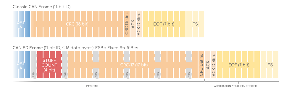
SBC: The Stuff Bit Count (SBC) precedes the CRC and consists of 3 gray-coded bits and a parity bit. The following Fixed Stuff-Bit can be regarded as a second parity bit. The SBC is added to improve communication reliability.
CRC: The Cyclic Redundancy Check (CRC) is 15 bit in the Classical CAN, while in CAN FD it's 17 bits (for up to 16 data bytes) or 21 bits (for 20-64 data bytes). In Classical CAN, there can be 0 to 3 stuff bits in the CRC, while in CAN FD there are always four fixed stuff bits to improve communication reliability.
ACK: The data phase (aka payload) of the CAN FD data frame stops at the ACK bit, which also marks the end of the potentially increased bit rate.
Overhead and data efficiency of CAN FD vs. CAN
As evident, the added functionality of CAN FD adds a lot of extra bits vs. Classical CAN - how can this lead to less overhead?
The answer is that it doesn't - see the below visualization of Classical CAN vs. CAN FD for 3 data bytes. In fact, the efficiency of CAN FD does not exceed Classical CAN until crossing 8 data bytes. However, by moving towards 64 data bytes, the efficiency can go from ~50% up towards ~90% (more on this below).
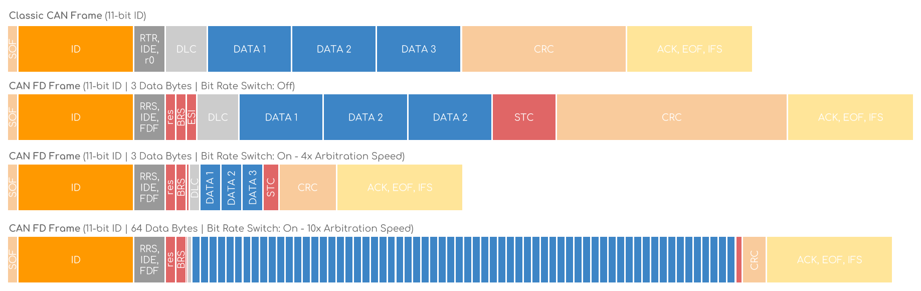
Need for speed: Turning on bit rate switching
As mentioned, sending 64 data bytes at regular speed would block the CAN bus, reducing the real-time performance.
To solve this, bit rate switching can be enabled to allow the payload to be sent at a higher rate vs the arbitration rate (e.g. 5 Mbit/s vs 1 Mbit/s). Above we illustratively visualize the effect for the 3 data byte and 64 data byte scenarios.
Note that the higher speed applies to the data frame section starting in the BRS bit and ending in the CRC delimiter.
Further, most vehicles today use 0.25-0.5 Mbit/s, meaning that with 5 Mbit/s CAN FD would 10x the speed of the payload transmission.
As mentioned earlier, Classical CAN and CAN FD nodes can be mixed under certain conditions. This allows for a step-by-step migration towards CAN FD, rather than having to switch every ECU in one go.
Two scenarios exist:
100% CAN FD system: Here, the CAN FD controllers can freely mix Classical CAN and CAN FD data frames.
Some nodes are legacy Classical CAN: Here, the CAN FD controllers can switch to Classical CAN communication to avoid error frame reactions from the Classical CAN nodes. Also, during e.g. ECU flashing, the Classical CAN nodes may be turned off to allow a temporary shift to CAN FD communication.
A confusing aspect of CAN FD is the max bit rate during the payload phase - as different articles mention different levels.
Some state that practical applications enable up to 8 Mbit/s and theoretically 15 Mbit/s. Others state up to 12 Mbit/s. Further, Daimler state that beyond 5 Mbit/s is doubtful - both as there's no standard for this and because low-cost automotive Ethernet (10 BASE-T1) is expected to limit the demand for CAN FD at higher speed.
So what is correct?
It depends. Looking at ISO 11898-2 (the transceiver chip standard), it specifies two symmetry parameter sets. It is recommended to use those with improved symmetry parameters, often advertised as 5 Mbit/s transceivers. The achievable data phase bit-rate depends on many things. One of the most important is the desired temperature range. Flashing of an ECU does not require the support of low temperatures. This implies that for ECU flashing, it is possible to go up to 12 Mbit/s. Another important bit-rate limitation is caused by the chosen topology. Bus-line topology with very short stubs allows significantly higher bit-rates versus hybrid topologies with long stubs or even stars. Most multi-drop bus-line networks are limited to 2 Mbit/s for a temperature range of -40 degC to +125 degC. CiA provides appropriate rules of thumb in the CiA 601-3 network design recommendation. This includes recommendations to set the sample-points in the data-phase.
For more technical details on CAN FD, we can recommend the below tutorials and guides:
- CAN FD Wiki: Contains e.g. a good comparison of CAN FD vs. CAN (Classical CAN bus)
- CAN FD logger: Our intro to logging CAN FD data incl. practical examples
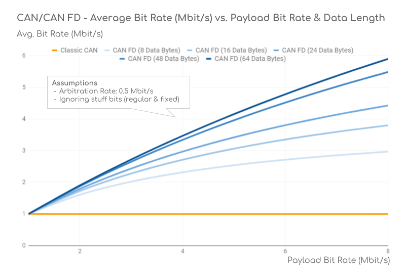
CAN FD calculator: Efficiency & baud rate
For a detailed understanding of CAN FD efficiency and average bit rates, we recommend to check out our CAN FD calculator.
CAN FD calculator
Examples: CAN FD applications
In short, CAN FD allows a system to handle more data at a faster rate.
This is vital for a number of increasingly relevant use cases:

Electric vehicles
EVs and hybrids use new powertrain concepts that require far higher bit rates. Added complexity comes from new control units related to the DC/DC inverter, battery, charger, range extender etc. By 2025 it is expected that the required bit rate exceeds CAN - and with the explosive rise in EVs, this may be the spearhead of the CAN FD roll-out.

ECU flashing
Vehicle software is becoming increasingly complex. As such, performing ECU updates via e.g. the OBD2 port can take hours today. With CAN FD, such processes can be made >4x faster. This use case has been one of the original drivers behind the demand for CAN FD by automotive OEMs.

Robotics
Several applications rely on time-synced behaviour - e.g. robot arms with multiple axles. Such devices often use CANopen and require multiple CAN frames (PDOs) to be sent by each controller time-synced (without interruption from higher-priority frames). By shifting to CAN FD, the data can be sent in a single frame for efficiency.

ADAS & safe driving
Increasingly, advanced driver assistance systems (ADAS) are being introduced in passenger cars and commercial vehicles. This pressures the bus load of Classical CAN, yet ADAS is key to improving safety. Here, CAN FD will be key to enhancing safe driving in the near future.

Trucks & buses
Trucks & buses utilize long CAN buses (10-20 meters). As a result, they rely on slow bit rates (250 kbit/s or 500 kbit/s as per J1939-14). Here, the upcoming J1939 FD protocol is expected to enable a significant improvement in commercial vehicle features, incl. e.g. ADAS.

Secure CAN bus
As shown in recent CAN hacker attacks, Classical CAN is vulnerable. If hackers gain access to the CAN bus (e.g. over-the-air), they could e.g. turn off critical functions. CAN FD authentication via the Secure Onboard Communication (SecOC) module may be a key roll-out driver.
Logging/streaming CAN FD data - use case examples
With the rise of CAN FD there will be several use cases for recording CAN FD data:

Logging / streaming data from cars
As CAN FD gets rolled out in cars, CAN FD data loggers and CAN FD interfaces will be key for OEM R&D and diagnostics
CAN FD logger
Heavy duty fleet telematics
IoT CAN FD loggers compatible with J1939 FD (flexible data-rate) will be key to future heavy duty telematics
j1939 telematics
CAN bus predictive maintenance
As CANopen FD rolls out, new industrial machinery will need CAN FD IoT loggers to help predict and avoid breakdowns
predictive maintenance
Vehicle/machine blackbox
A CAN FD logger can serve as a 'blackbox' for e.g. new prototype vehicles, providing data for diagnostics and R&D
can bus blackboxDo you have a CAN FD logging use case? Reach out for free sparring!
Contact usCAN FD logging - practical considerations
When logging CAN FD data the following considerations are relevant:
Before the ISO 11898-1:2015 update, the CAN FD standard had a weakness related to error checking. Controllers adhering to the updated standard are sometimes referred to as "ISO CAN FD".
When recording data from an early prototype CAN FD system you may therefore need to turn on "NON-ISO CAN FD" mode if your device supports this.
By default, your CAN FD data logger will be able to handle both Classical CAN and CAN FD data messages - without having to be pre-configured between them. Similarly, you won't have to pre-specify whether bit rate switching is on/off for pure logging purposes.
However, when you transmit data to the CAN bus, you'll need to specify whether to use bit rate switching or not. If enabled, your data payloads are transmitted at the system's 2nd bit rate, which will typically be 2 or 4 Mbit/s.
CAN FD minimizes the need for handling multi-packet messages. This can greatly simplify the software development for converting raw CAN FD data to human-readable form, to the benefit of end users of CAN FD analyzers.
Further, the standard CAN database format, DBC, also supports CAN FD conversion rules. As such, it's always recommended that you collect your scaling rules in a DBC file to enable easy transition between various CAN software like e.g. asammdf, webCAN etc.
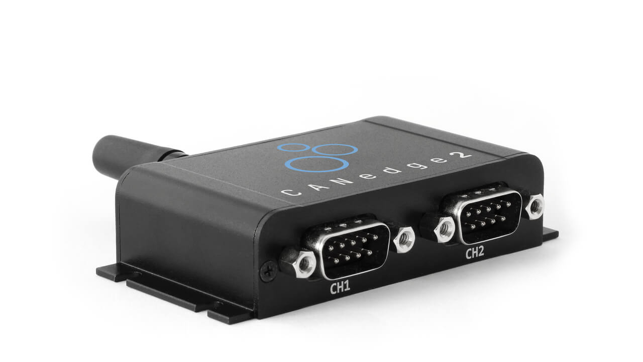
Example: CANedge CAN FD logger
The CANedge lets you easily record CAN FD data to an 8-32 GB SD card - or use the CANedge2 / CANedge3 to also offload it via WiFi/LTE. Simply connect it to your CAN FD application to start logging - and process the data via free software/APIs.
Buy now CAN FD data loggingExample: CANsub CAN FD interface
The CANsub.2/CANsub.4 lets you stream 2-4 x CAN FD channels in real-time via USB or Ethernet - viewing the live frames and DBC decoded signals directly in your browser via webCAN.
Buy now webCAN software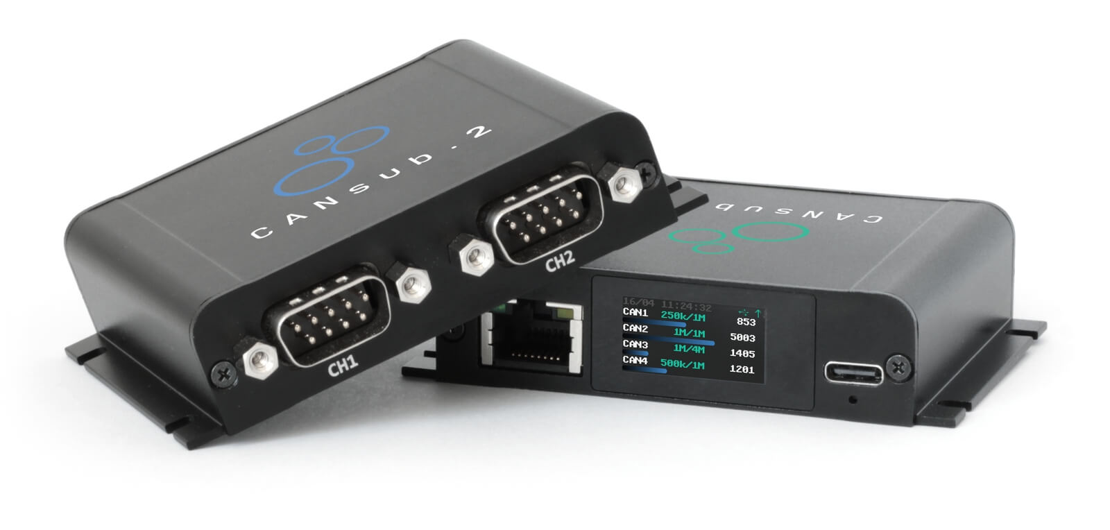
CAN FD - outlook
CAN FD has been predicted to take over Classical CAN:
- The first CAN FD capable cars were sold in 2019/20
- CANopen FD has been adapted via CiA 1301 1.0
- J1939-22 uses CAN FD data frames
- CAN FD is increasingly used in XCP on CAN for e.g. DAQ
- Most CAN hardware/software now support CAN FD
With that said, it is unclear if CAN FD will be the replacement to Classical CAN. Work has already begun on CAN XL, a successor to CAN FD - while many believe some variant of Automotive Ethernet will instead be the ruling protocol in the coming years.
In our own experience at CSS, we do see CAN FD in practical use across OEMs (and we use it in e.g. our sensor-to-CAN products) - but it constitutes less than 5% of customer use cases, with Classical CAN still dominating - including for new development efforts.

For more intros, see our guides section - or download the 'Ultimate Guide' PDF.
Need to log CAN FD data?
Get your CAN FD logger today!