CAN Bus Reverse Engineering with AI [Claude Code]

Can an AI agent reverse engineer your CAN bus data?
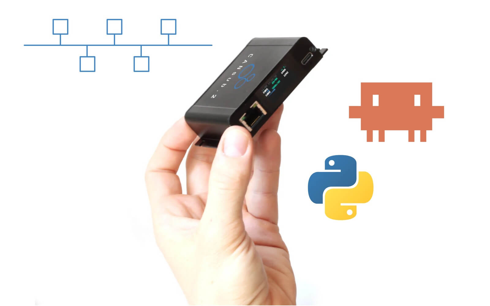
In this article, Martin Falch uses our CANsub CAN bus interface together with python-can and a custom Claude Code 'skill' to reverse engineer multiple CAN bus signals.
For basics on CAN bus reverse engineering see our CAN sniffer article, which covers the classic human-analysis approach. This article shows what is possible with an LLM.
Spoiler alert: It works extremely well, as evident from our practical showcases - this concept is the future of CAN sniffing.
But don't take our word for it - this guide will help you try it yourself right now!
The challenge: CAN bus reverse engineering is hard
Reverse engineering a proprietary CAN signal by hand is notoriously tough.
A typical bus produces thousands of frames per second across dozens of CAN IDs, and the parameter you care about is hidden somewhere in the raw bytes.
Extracting it is like finding a needle in a haystack:
- Trawl huge volumes of CAN frames to spot which CAN ID might contain your signal
- Guess the exact start bit and bit length of the field inside the payload
- Figure out the byte order (little vs. big endian) and whether the value is signed
- Solve for the scale and offset that map the raw value to a physical unit
- Repeat this trial-and-error loop until the decoded result finally looks right
This is slow and demands real expertise - and often takes hours per signal.
Scripting the analysis in e.g. Python helps, but also demands specialized skills. Further, there is no single script that decodes any signal, each has its own quirks.

The solution: CANsub + a Claude Code skill
To address these challenges, I wanted to see if AI/LLM tools could help non-technical users reverse engineer CAN signals. To test it, I built a Claude Code skill and used it to reverse engineer a diverse set of signals with the CANsub.2 and python-can.
Note: The goal here is not to push this specific skill (though you are welcome to use it). It is to show a conceptual workflow.
In the following sections I explain how it works, how you get started - and practical showcases of the workflow in action.
How does it work?
Below I outline briefly what the skill does under the hood - from your first prompt to a ready-to-use DBC file.
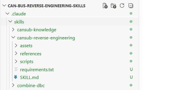
1: The skill itself
The Claude Code skill is just a folder with instructions for the LLM, some context material and a collection of small Python scripts the LLM can use. Following your prompt, the AI agent follows the instructions step by step and decides on what tools to use dynamically based on the context and your data.
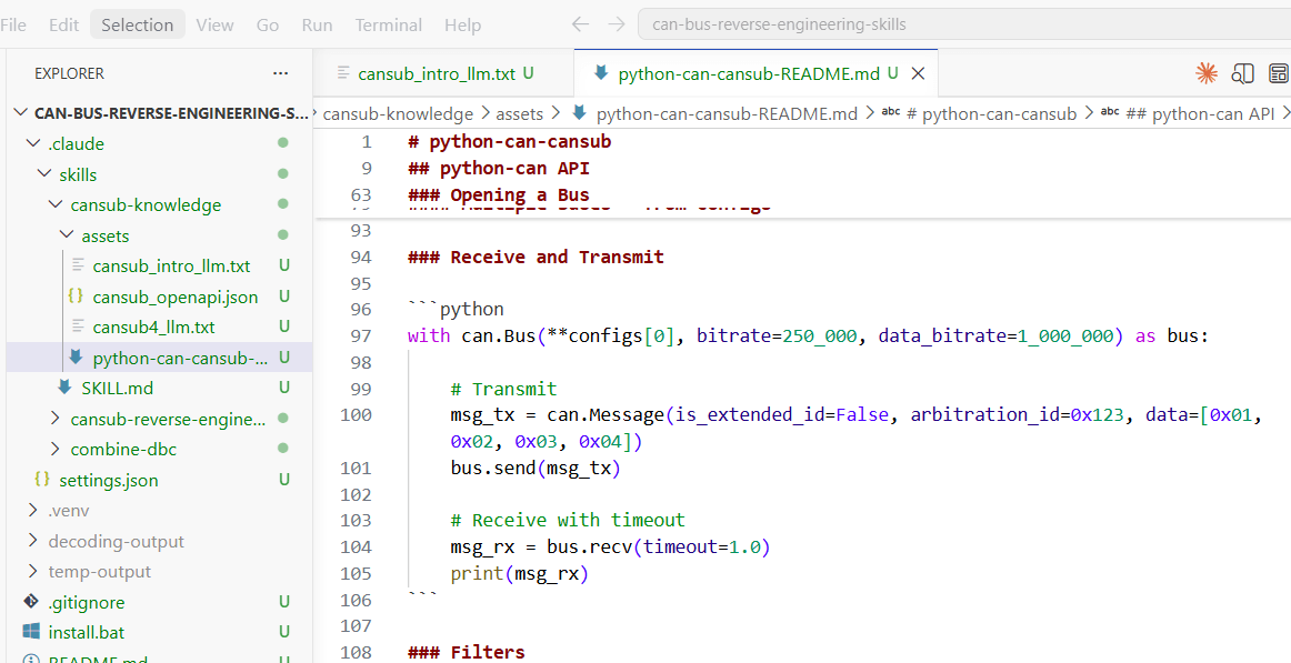
2: Knowledge material
The skill includes knowledge material for the LLM: How the CANsub and python-can work, our standard OBD2 DBC for decoding OBD reference signals - and our CAN sniffer article for basics. This helps the AI agent make sensible decisions and hallucinate less.
3: Two entry points (log/stream)
Importantly, every CAN sniffing analysis needs a 'reference' signal to compare the raw proprietary CAN data against. The skill supports two approaches:
- You provide a raw CSV log file with the proprietary CAN data and a CAN-based reference signal (e.g. OBD2 vehicle speed)
- If the above is not possible, you create a reference signal live yourself via an external source as per below
4A: Vision-based reference signal (OCR)
If your signal has a visible physical value - like 'X km/h' on your vehicle dashboard, diagnostic tool, app etc - you can use a video-recording as a reference signal. You record a proprietary CAN trace CSV with the CANsub while e.g. filming the vehicle dashboard with your iPhone. The skill uses Optical Character Recognition (OCR) to extract a digitized reference signal for the subsequent analysis.
4B: Human-based reference signal
For signals without a ready CAN reference (and with no display value), the skill can launch a small browser app to enable 'human input' that mirrors the real-world value, e.g. opening/closing the door or the position of a steering wheel. The app records your input with timestamps, synced to the CAN trace, as a reference to analyze against.
5: Analysis (AI + Python)
With a trace and a reference in hand, the LLM performs a step-by-step analysis using various Python scripts. This includes lining up every 'candidate field' in the data against your reference and ranking them by how closely they move together. It then zooms in to pin down the exact start bit, length, byte order and sign. Next, the skill determines the scale and offset. Finally, various sanity checks and corrections are performed.
6: Output - verification plots & DBCs
With the analysis complete, the AI agent writes a ready-to-use DBC file in an 'application/signal' subfolder. It also produces a 'result plot' showing the reference vs. decoded signal for your review. As you decode more signals, you can ask Claude to merge them into a combined application DBC, which you can load straight into webCAN to plot and verify your decoding live.
I wrote our original CAN sniffer article some years ago and recently updated it with our launch of the CANsub. Since the initial draft, I have naturally started using various AI tools - see e.g. my articles on ChatGPT + CAN, Grafana Assistant and more. I now use Claude Code + skills daily and thought it would be a great 'infrastructure' for CAN sniffing.
Below is how I approached the skill development:
- I deliberately did not review/create the Python scripts/tools or SKILL.md myself
- I began by sharing relevant context (our CANsub 'Docs for AI', our python-can-cansub README etc)
- I then asked Claude to help reverse engineer specific CAN signals (I provided the data/reference inputs and knew the answers)
- I reviewed the results, highlighted problems and asked the LLM to help resolve them
- This process was then repeated several times with a diverse set of challenges
- Throughout, the skill was also evaluated 'out of sample' to avoid over-fitting to the examples I used for the skill development
The process took me probably 5-10 hours - I intentionally did not polish this.
The skill could be refined much more (PRs are welcome), but even this basic version performs really well.
In practice this would involve multiple challenges:
- Context: First of all, AI tools like Claude and ChatGPT work best when their 'context windows' are not filled up with irrelevant information. The more text/data you provide them directly, the 'dumber' they will appear. Instead, you need to provide them the relevant context - e.g. summary statistics, specific scripted outputs etc. This lets them focus directly on the key insights
- Tools: If you work with Claude/ChatGPT in your browser, it may automatically use tools such as Python when it is sensible - e.g. if you upload a very large CSV file. And as per my separate ChatGPT + CAN article, the results can be quite impressive. However, when you start up a new conversation, the chat bot will essentially need to re-generate each script it uses from scratch - and you'll get rather inconsistent/slow results because of this. Claude Code's skills concept is a way to 'memorize' tools/workflows/context that will be repeatedly useful - and thus also enables easy iterative improvements to be made
- Local access: Even if your browser-based ChatGPT used tools and skills to analyze provided data, it would still be unable to directly control your CANsub, for example. It would also be more time-consuming as you would need to upload/download files repeatedly. Having a local workspace where you leverage the LLM is drastically more effective
Why the CANsub is ideal for this
This workflow can be adapted to any python-can interface, but the CANsub is especially well suited for AI-driven reverse engineering:
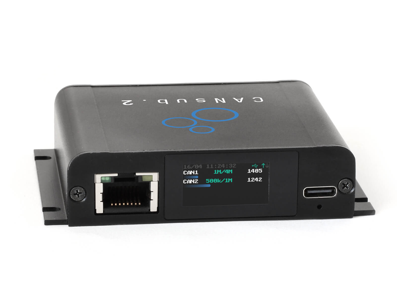
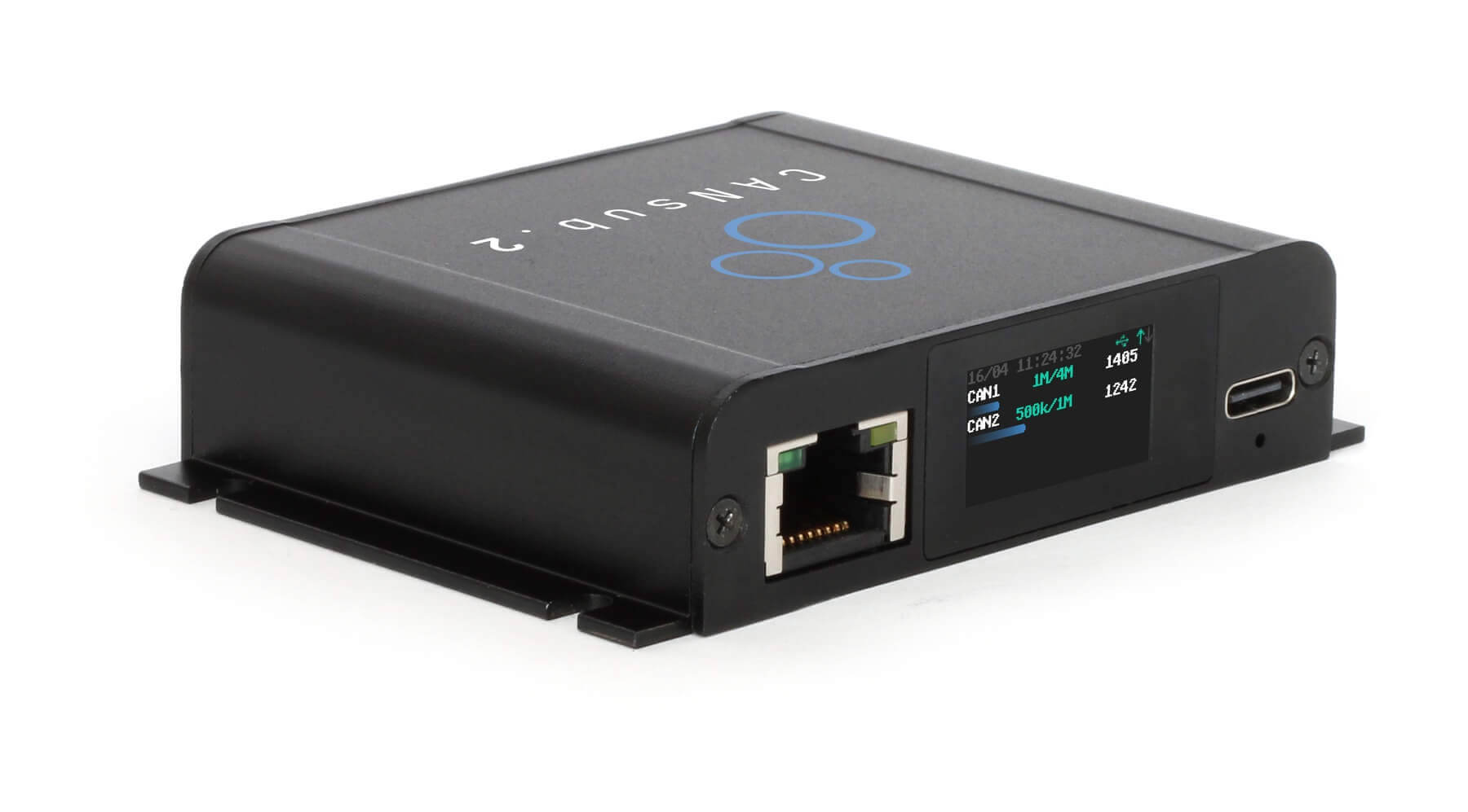
LCD status at a glance
In LLM workflows it can be unclear what is happening. The LCD shows it instantly: Are we recording, what is the busload, are we in silent mode, are we stuck with CAN errors etc
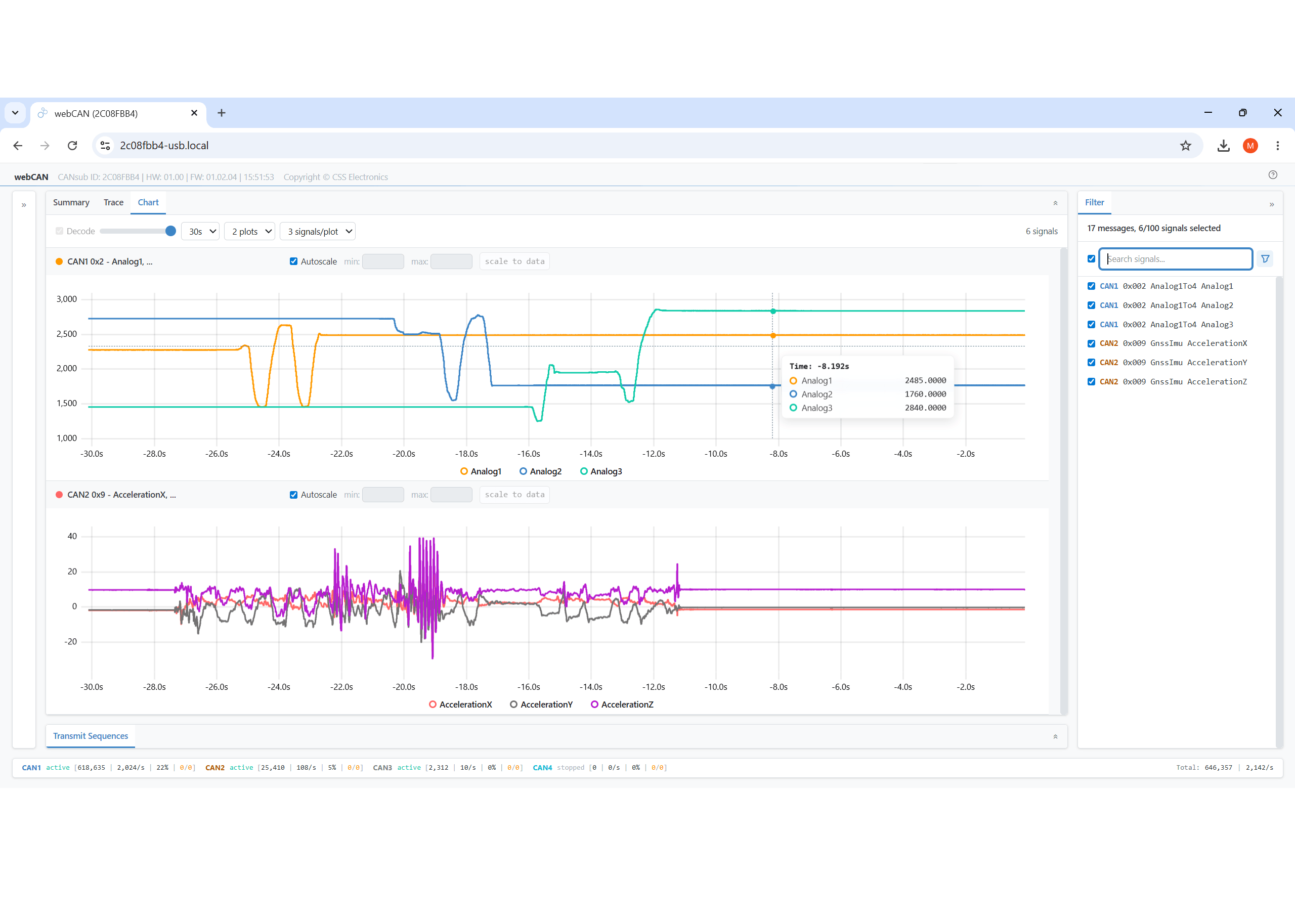
webCAN test & export
webCAN lets you stream and visualize raw/decoded CAN data - and export trip data to CSV for use by your LLM. It's the perfect companion tool for LLM workflows
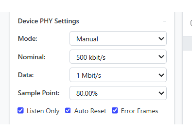
Silent mode & errors
The CANsub's silent (listen-only) mode lets you observe a live bus safely without disturbing it, and error frame logging is critical for spotting bus issues during analysis
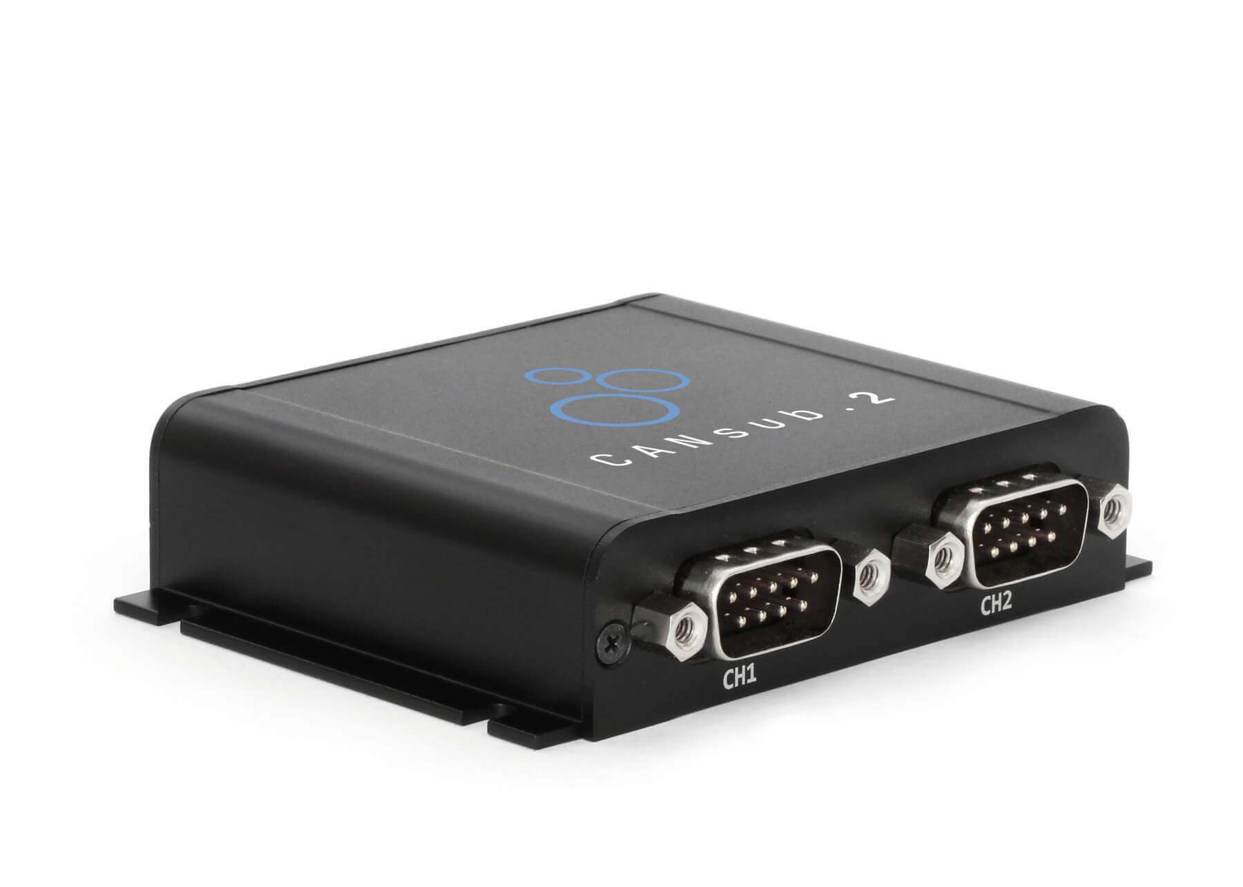
Dual CAN channels
Many car OBD2 connectors expose no proprietary CAN. With 2 x CAN you can log OBD2 on CAN1 and proprietary CAN on CAN2 via a contactless adapter for export to one CSV
How to get started
If you wish to follow this workflow as-is I recommend getting below items:
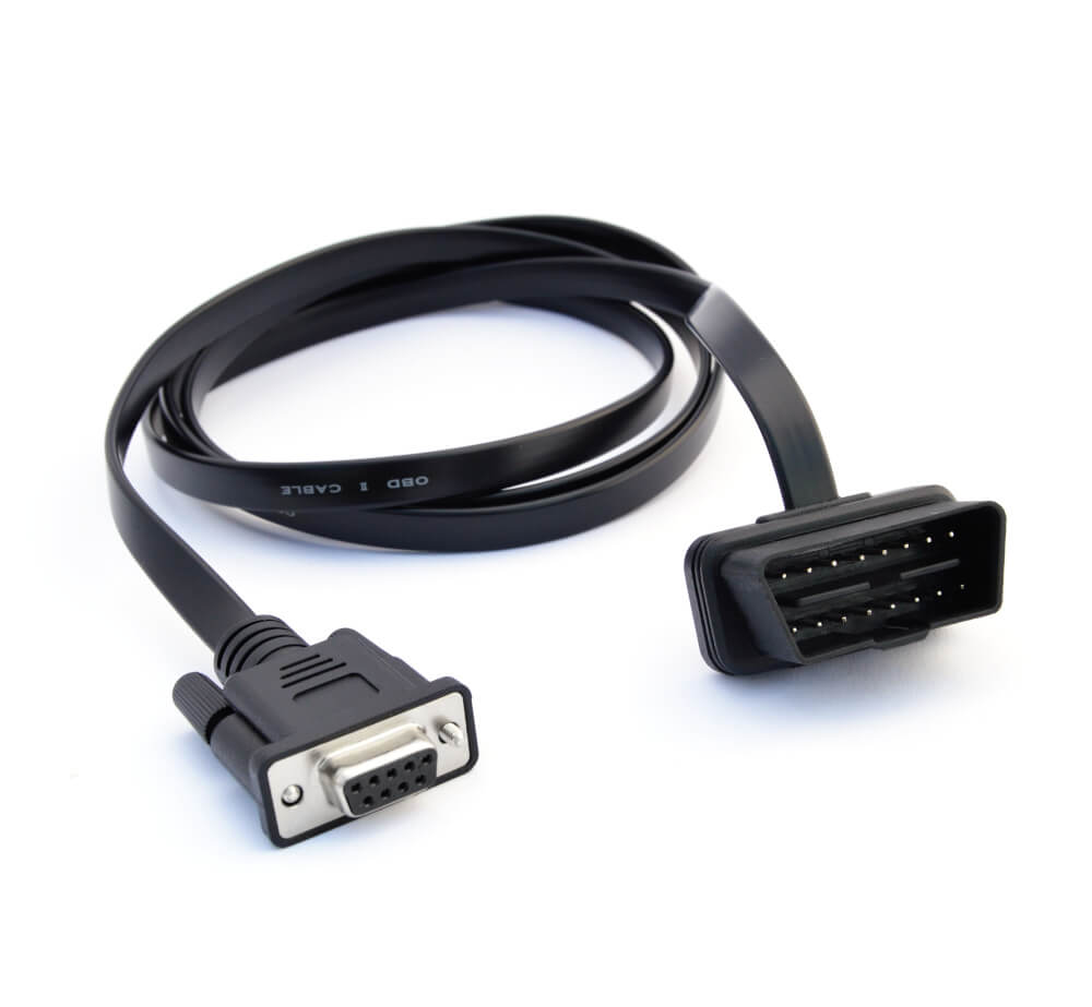
- 1 x CANsub.2 + 1 x OBD2-DB9 adapter
If your car does not expose proprietary CAN via the OBD2 connector, add below:
- 1 x contactless adapter + 1 x receptacle-DC adapter
Next, follow the README on the can-bus-reverse-engineering-skills GitHub (10 min).
Tip: You can try the skill with our sample CAN+OBD2 data (see the README).
Maybe you're familiar with using ChatGPT in your browser - but you've never tried an AI coding tool like Claude Code. If so, this may seem daunting at first.
However, if you follow the README steps you'll find that it's quite simple to get started. It's essentially just installing a couple of things - and then you are back to your normal prompting process, just directly on your PC via Visual Studio Code. And now your chatbot can access folders, files, Python - and your CANsub.
And, should it happen that this article is your onboarding point for starting to use Claude Code + skills in your daily work? Well you can thank me later.
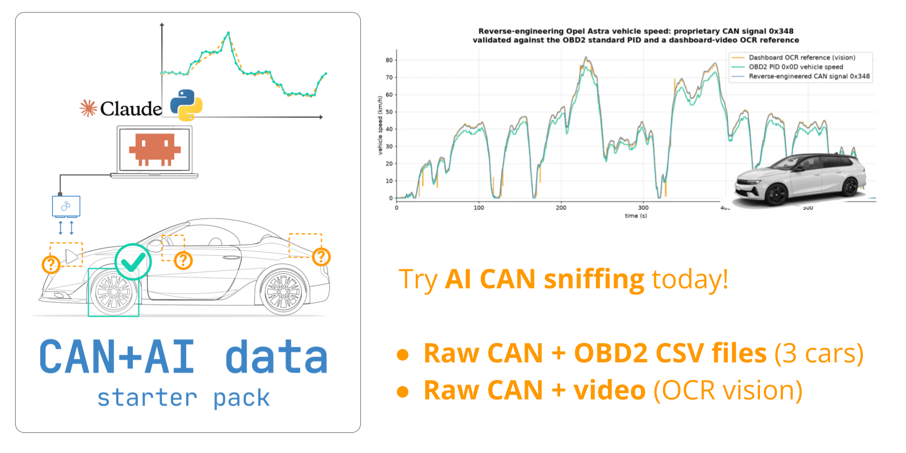
Get your 'AI CAN sniffer data pack'
Want to reproduce the showcases from this article yourself?
Download your 'data pack' including:
- 3 x raw car CAN data with matching OBD2 reference signals
- Opel Astra CAN data + dashboard video for vision workflow
Use this to replicate two of our showcases - and potentially reverse engineer new CAN signals!
Reference signal: CAN-based vs. external
Before you start, determine how you will provide your reference signal:

CAN-based reference (log files)
If the target signal has a direct CAN based and decodable reference/proxy (such as OBD2 speed/RPM or GPS-to-CAN speed), always use this. You log the reference CAN signal alongside the proprietary CAN and the skill extracts the reference straight from the log. This is the most precise option, since the reference is machine-accurate. The CANsub's CSV export in webCAN makes capturing this log trivial.

External reference (streaming)
If no CAN based reference exists, generate one yourself in real time via e.g. the 'reference generator' app in the skill or by filming a physical value like your car's dashboard speed and using the vision-recognition tool of the skill. You mirror the real-world value as you stream. This is more noisy than a CAN based reference, but it is more agnostic and works for signals you cannot reference any other way.
It may seem silly to spend time reverse engineering proprietary CAN signals that you are already able to request and decode via OBD2. However, the proprietary CAN signal equivalent is often more precise (e.g. a resolution of 0.1 km/h vs. 1 km/h) and available at higher frequency (e.g. 10 Hz vs. e.g. 0.2 Hz for OBD2).
The frequency is particular relevant if you need to request many OBD2 PIDs, as you need to space them out by e.g. 0.5 seconds each. This means that requesting 10 x OBD2 PIDs requires a 'period' of 10 x 0.5s = 5 seconds. In such a case, you can only observe OBD2 speed once every 5 seconds - which can be a problem in many use cases.
Finally, proprietary CAN signals can be silently recorded by e.g. the CANsub or a CAN logger like the CANedge. This means you can avoid requesting OBD2 data from the vehicle, which simplifies installation, injection risk, battery drain mitigation and more.
It is naturally easier to isolate the relevant signal if you provide a highly diverse and full-range representative set of reference data to compare against the corresponding raw proprietary data.
In my experience, if you have a CAN reference signal like OBD2 speed, you can get good results even with short trips (e.g. 5 min) if your trip has good variation (e.g. standstill, acceleration, deceleration, different stationary levels at e.g. 10 km/h, 20 km/h, ... etc).
For manually injected signals like moving a slider, it depends on the signal/context. In my tests I was able to succeed with just a brief 1-2 min injection sequence - but in more noisy/difficult scenarios (e.g. many active ECUs) I suggest e.g. 5-10 min sequences.
Once you start successfully reverse engineering CAN signals from e.g. your car, make sure to provide your growing application DBC file to Claude as input for subsequent analyses. This helps the LLM eliminate already-known signals - but more importantly, these signals can often serve as reference signals for new target signals due to their close relationships. For example, knowing vehicle speed already gives you immense context on all subsequent decoding efforts.
3 x showcases: Reverse engineering CAN signals with AI
Below are a few concrete examples I ran. They are deliberately diverse, and as you would expect, some work better than others. The aim is to give you a realistic sense of where this method shines and where it gets harder.
1: Speed & RPM from OBD2 in <5 min
This is the 'sunshine scenario': A CAN based reference is available. Using the CANsub and webCAN, you perform OBD2 requests for speed and RPM and log the responses in parallel with the proprietary CAN traffic. The skill then decodes the OBD2 data and uses it to locate the matching proprietary signals.
To showcase this workflow, I used some old CAN+OBD2 log files to test it on. My prompt to Claude is simple:
Reverse engineer Speed and RPM from the proprietary CAN data found in Mercedes-E350-2010-obd2-can.csv (contains OBD2 reference data).
As per the video, Claude reverse engineers the proprietary Speed and RPM perfectly within <5 min!
Claude also outputs signal DBC files and auto-merges them into a Mercedes DBC file - ready for use in e.g. webCAN.
Technical deep-dive: What's actually happening under-the-hood?
I also setup the skill to output some 'analysis visualizations' to show what Claude is actually doing under-the-hood. Of course, Claude uses the JSON-equivalent data behind these plots - but below I'll explain briefly the logic of each step.
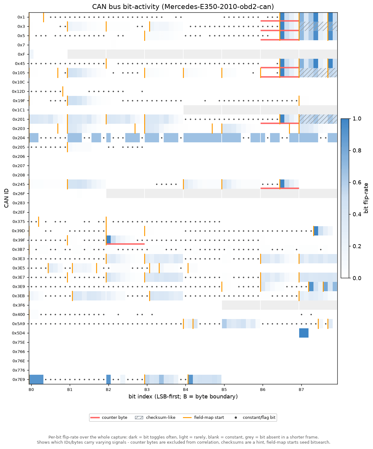
Step 1: Survey the bus activity
The first plot is a 'bit-activity heatmap' of the entire raw CAN bus. Every CAN ID is a row, every bit a column, and the shading shows how often each bit changes. It's an LLM-friendly and more comprehensive statistical version of SavvyCAN's 'sniffer tool'.
In one glance it separates the messages that are constantly varying (good candidates for a live signal) from the static ones - and it flags rolling counters and checksum-like bytes so they can be excluded from subsequent analyses. This is how Claude narrows tens of CAN IDs down to a short list worth investigating, before it ever looks at the reference signal.
For every CAN ID the script notes the basics - how many frames arrived, how often (and how regularly) they come in, and how long the payload is. The key measurement is the flip rate of each individual bit: How often does each one switch between 0 and 1 from one frame to the next?
That single number tells you what each bit is doing. Bits that never change are just padding or fixed values. A bit pattern that ticks over at a steady, clock-like rhythm is a rolling counter (a frame number that wraps around), and a byte that jumps to a random-looking value on every frame is a checksum (an error-check). Neither is a real measurement, so both are set aside before the search - that way they can't be mistaken for the signal we're after. Of course, there can be exceptions to these rules - but some assumptions are necessary to eliminate certain bytes from our analysis.
For messages that pack several values tightly together, the script also takes a first guess at where each value starts and ends. The trick: Within a number, the lowest bit flips fastest and the highest bit flips slowest, so a spot where the flipping suddenly speeds up again is likely the start of the next value. It's only used as a hint, but it helps when values don't line up neatly on byte boundaries.
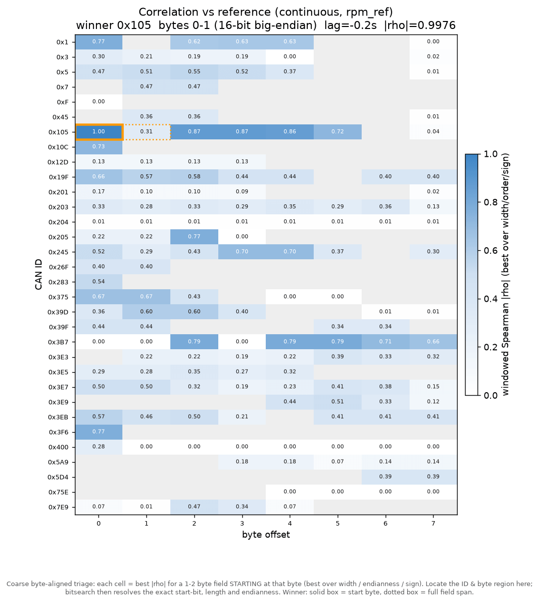
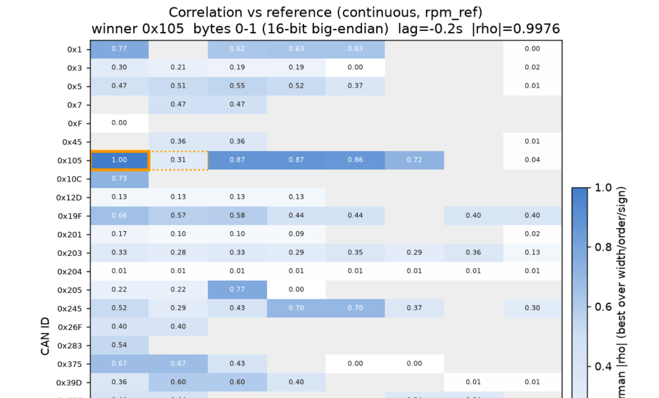
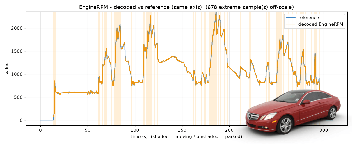
Step 2: Correlate against the reference
Next, each candidate field is lined up against the decoded OBD2 reference (here engine RPM) and ranked by how closely the two move together over time. This correlation heatmap scores every CAN ID and byte position - and outlines the best match (the 1st byte of a potential multi-byte signal in solid outline).
This analysis guides Claude towards the right message - the CAN ID that carries the signal - and gives a first hint of which byte holds it. The byte is only a starting point though: The exact start bit & bit length are identified in the next step.
This script takes each 'candidate block' in the data. A block is defined as a specific CAN ID, start byte, width (1 or 2 bytes) and byte order. The script reads out the decimal value over time. Note that this stage deliberately stays on byte boundaries to keep the search fast - the exact start bit and bit length within the block are nailed down in step 3. Both this raw series and the reference are then resampled onto a shared, fixed-rate timeline (a 'sample-and-hold' grid) so the two can be compared point-for-point, scoring how closely they rise and fall together over time.
The agreement is measured with a specific correlation methodology called windowed Spearman rank correlation. This rewards a field that rises and falls together with the reference regardless of the still-unknown scale/offset or mild nonlinearity. Further, the script takes the median across many overlapping windows to make the score robust to local glitches or imperfect human input.
The script also involves a few extra safeguards. For example, to absorb the 'reaction delay' between the reference and the bus, the reference is slid across a small range of time lags and the best-scoring lag is kept. Further, both signed and unsigned interpretations are tested, and a reference-free 'plausibility' prior (does the decoded series wrap or jump around like noise?) breaks ties so an implausible byte-aligned read can't top the list. Counter bytes flagged by the survey are skipped, and high-confidence 'signal unavailable/invalid' values are masked out before scoring. This final step is key since many CAN based protocols introduce 'extreme values' for periods where the signal may not be available, even if a reference signal may be. In this concrete example, such outliers had to be removed for both RPM and Speed.
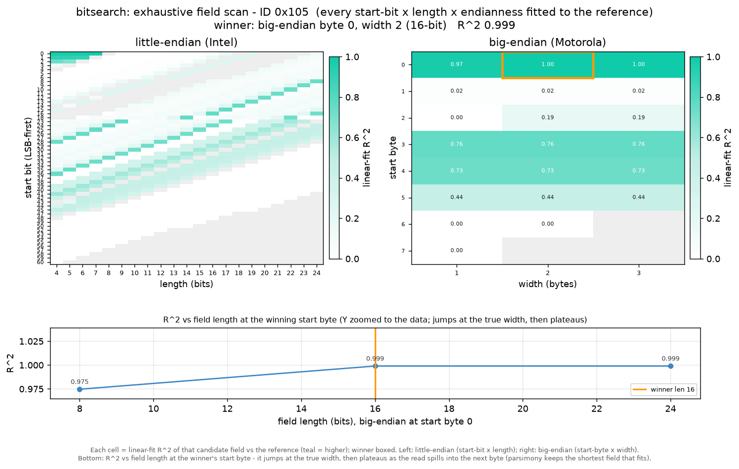
Step 3: Bitsearch for the exact field
With the CAN ID known, the bitsearch exhaustively tests every plausible field: Each start bit, each length, both byte orders (Intel/Motorola) and signed/unsigned.
The grid shows the goodness-of-fit (R²) for each combination and the identified winner (solid highlight) - here a 16-bit, big-endian value. If both a 2-byte and 3-byte signal provide nearly equal fit, the shorter signal is preferred. This step also helps the LLM identify signals that cross byte boundaries, for example.
Step 2 only narrowed things down to 'roughly the right byte'. The bitsearch step now pins down the exact field (i.e. bit start and length) inside that one message. To do so, it tries every possible combination of where the value starts, how many bits long it is, which direction the bytes are ordered (Intel vs. Motorola), and whether it can go negative. To save effort it only considers bits that actually change - there's no point testing a stretch that includes a bit which is always stuck at the same value. This leverages the initial survey in step 1.
Each combination gets a score for how well it fits a straight line against the reference signal. The idea is simple: If you've found the real field, then plotting it against the reference should give a clean, straight-line relationship (twice the raw value means twice the real-world value). A combination that only captures part of the value, for example, won't line up as nicely. The 'looks-real' and same-direction checks from the previous step help break any near-ties.
One last rule guards against a common issue: When in doubt, pick the shorter field. If two candidates fit equally well, the longer one has usually grabbed a few bits of a neighbouring value by accident (imagine reading the left and right wheel speed as one number). When those extra bits don't improve the fit we select the shorter option.
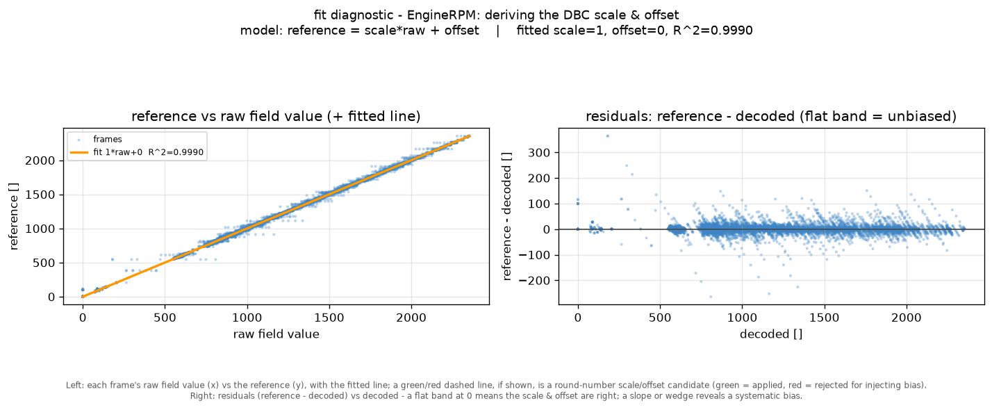
Step 4: Fit the scale & offset
The final step turns the raw field into a physical value. The decoded raw values are plotted against the reference and a straight line is fitted to derive the scale and offset that go into the DBC - with the residual panel confirming how tight the fit is.
The skill also sanity-checks the result against physical anchors to e.g. ensure a decoded Speed signal does not return a non-zero km/h when the OBD2 speed is 0 km/h. Further, the skill will attempt to round scale/offset values within certain thresholds.
At this stage of the analysis, the skill has identified which bits hold the signal, but not what they mean in real physical value terms. To finalize the signal, we need to identify the scale and the offset - see also our intro to DBC files.
To achieve this, the script performs a two-step analysis:
- Scale: The script plots the reference against the raw value to get a straight line - the scale is its slope. For robustness, the script measures the slope between many pairs of points and takes the median
- Offset: With the slope fixed, the offset is simply how far that line sits above or below zero - found as the typical gap between the reference and scale × raw
Finally, two sanity checks help keep the result sensible:
The first rounds the scale to a value an OEM would actually use (e.g. 0.1 instead of 0.0999281) - but only if this rounding barely changes the result.
The second makes sure the signal reads a known value at a known moment - most often zero when the vehicle is standing still. This catches a subtle problem: A decode can match the reference almost perfectly and still read something impossible like −1.6 km/h while parked, so the line is re-fitted to pass through that real-world anchor point.
2: Speed via vision OCR
But what if you do not have a CAN-based reference signal?
Elon: "Well, have you thought about ..."
Sigh, yes Elon we know - we'll use 'vision' to solve it.
If your car/truck/machine/... provides a real-time observable display value for your target signal, you can film this value and record the raw CAN bus trace in parallel.
The obvious example is from a car's dashboard - but this could also be e.g. a proprietary OEM scan tool, a smartphone app etc.
To show this in action, I got access to an Opel Astra with ~90 unique proprietary CAN IDs - and a dashboard showing speed.
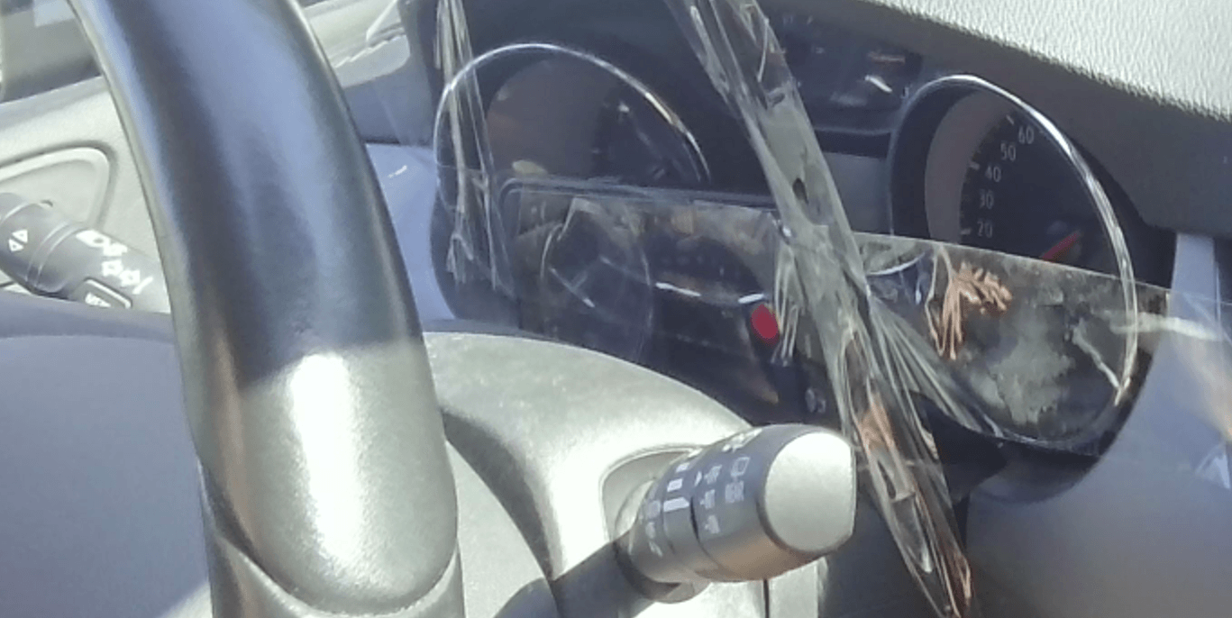
As an initial step, I gaffa-taped my iPhone to film the dashboard speed readout while recording the raw CAN bus data via the CANsub and webCAN. Not my best installation ...
For proper setups I recommend a USB-webcam connected to the same laptop as the CANsub, as this will also ensure both data sources share the same absolute timestamps.
Next, I drive a 10 min trip with speed varying from 0 to 80 km/h.
Now that my video + data is ready, I ask Claude:
Help me reverse engineer Speed from my Opel Astra. I have put the raw CAN data in opel/ along with a video of the speed from my car's dashboard.
As per the initial video, Claude recognizes this as a vision-based workflow. The LLM starts by snap-shotting some video frames to determine the coordinates of the speed value in the video. After this it runs the Python-based Optical Character Recognition (OCR) script. Once done, Claude opens a 'vision reference review' tool so that I can confirm that the OCR-based signal is OK.
OCR works best if you have a clean video from a mounted stable camera - and if you record when it's dark outside. My setup was probably close to worst case, yet the OCR methodology is surprisingly robust - and the subsequent correlation analysis just requires that the signal is 'good enough', not perfect.
After I confirm the vision-based signal, the process is identical to example 1 - i.e. Claude does the various analyses and decodes the proprietary speed signal without issues.
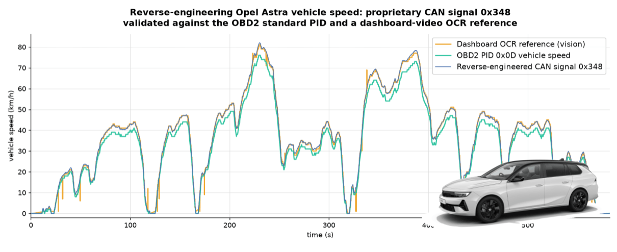
To illustrate the validity, I plotted the proprietary speed, vision-based speed and OBD2 speed. See my comments below.
Note that I deliberately filtered out the OBD2-based speed from this analysis in the CSV data I provided Claude, as the purpose was to prove that OCR-based speed was sufficient. As a result, Claude scales the proprietary speed to match the scaling of the observed dashboard speed, which is evidently a bit above the OBD2 speed throughout. The reason for this is because OEMs are legally required to ensure the dashboard speed always equals or exceeds the true speed (by up to 10%), as per UN R39. In my case the factor was 7%, but this could differ in other cars and is one limitation to be aware of when using the vehicle display as the reference signal.
3: Gauge position via human input
What if we want to reverse engineer a pedal position, steering wheel angle, door locks or similar? Here we may not have a CAN-based signal like OBD2, nor a way to film a digitized value corresponding to the signal.
For such cases we need to generate the reference signal based on raw, noisy human input. Ugh.
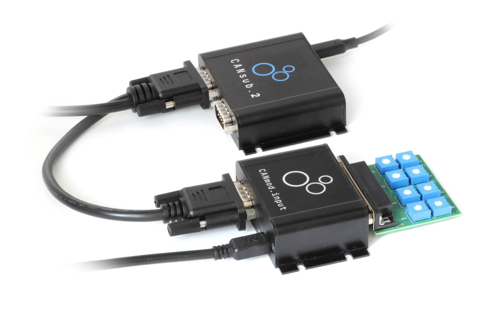
For demo purposes I use our CANmod.input sensor-to-CAN module with a potentiometer board connected to its DB25 connector. The board has 8 gauges that I can rotate, each producing a voltage output that the CANmod converts into a CAN signal value. Of course, I know the 'true DBC' for the CANmod.input in this case - but Claude does not.
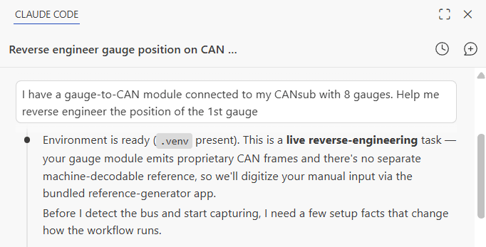
My prompt looks as below:
Result: Claude single-shot decodes the 1st gauge signal - and even extrapolates this to the remaining 7 gauges.
Let's deep-dive a bit on the steps. As shown in the video, Claude verifies that I am now looking to live-stream data via the CANsub - not analyze log files. Using the CANsub's python-can integration it auto-detects my device, auto-detects the bit-rate and does a quick analysis of the raw data. However, to progress the LLM needs a reference signal.
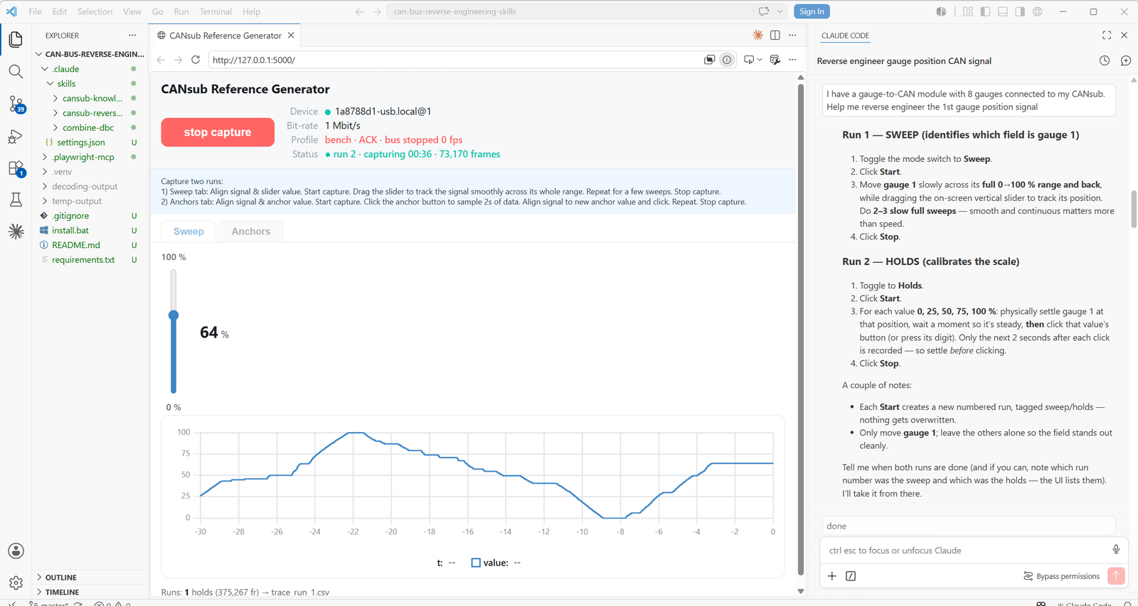
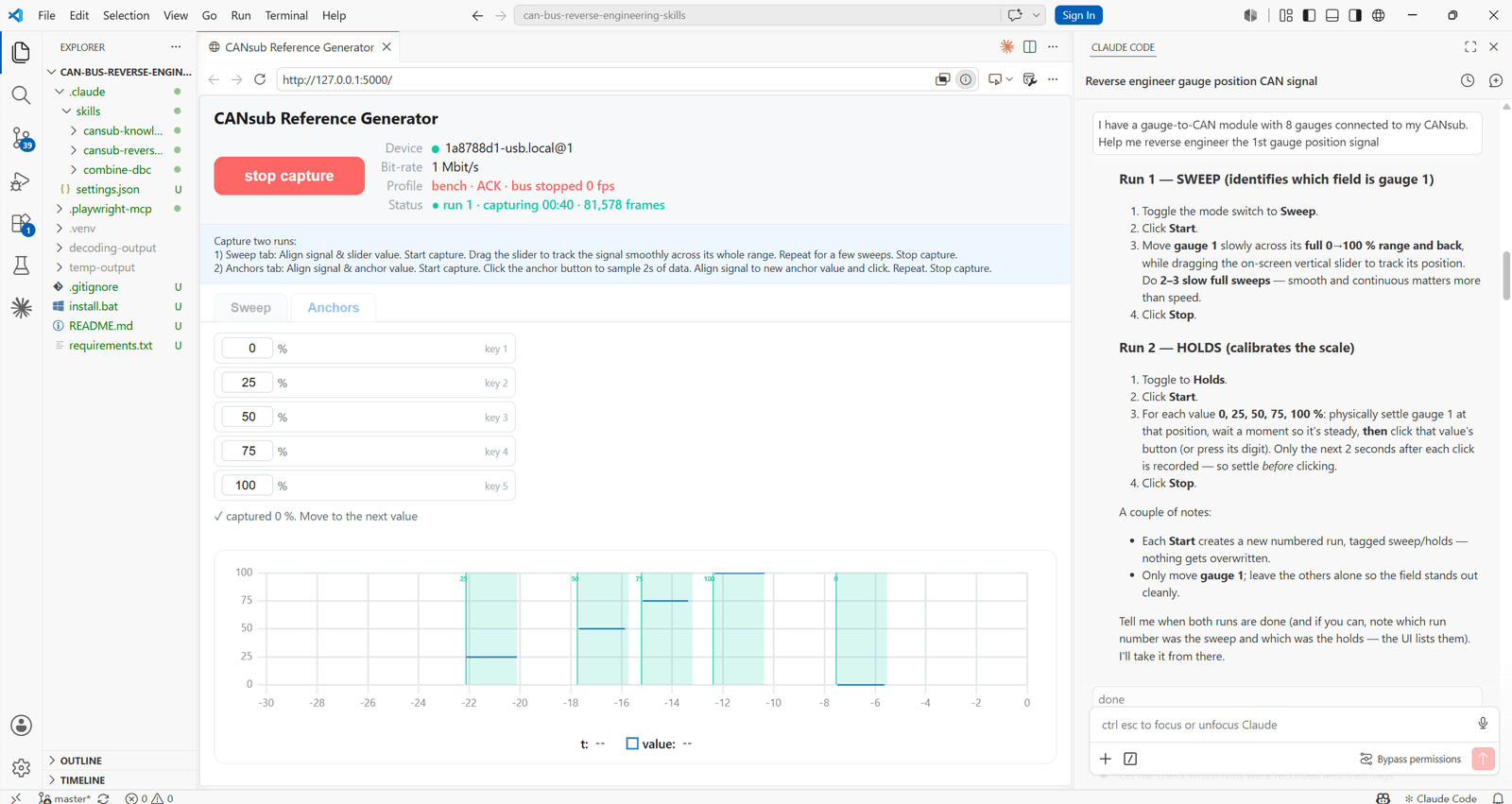
The CANsub Reference Generator
A key difference vs. example 1 and 2 is that I have no CAN/vision based reference signal - instead I have to create my own. For this purpose, the skill includes a 'CANsub Reference Generator' app.
The app simply provides buttons/handles that let me 'digitize what I see in the real-world' - thus allowing Claude to see this.
Based on my context, Claude pre-fills the app with suitable values, so all I do is capture the data for the analysis. I am asked for two things: A 'sweep', where I drag a slider in sync with turning the gauge, and a set of 'anchor' points, where I hold the gauge at 0%, 25%, 50%, 75% and 100% and sample 2 seconds at each. The combination of these two inputs serves as our reference signal. As the video shows, matching the sweep precisely is tricky, but the skill is built to tolerate this.
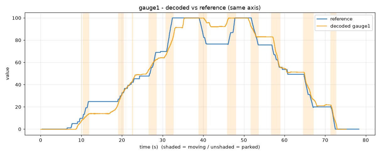
Despite the noisy reference, the result is again correct decoding of the 1st gauge. Further, from the analysis Claude correctly asserts the probable location of the remaining 7 gauges - allowing me to simply ask it to produce the combined DBC off that hypothesis. As part of this, Claude does a quick sanity check to verify that the decoding logic is consistent vs. the data.
Real-time validation via webCAN
To properly validate the reverse engineered DBC file, I open my browser and enter my CANsub URL to access webCAN. Here I load the new DBC file and plot the resulting decoded data while adjusting the gauge positions - enabling me to verify that everything looks as expected.
Key takeaways
Overall, I think this concept works extremely well:
- If you have a clean CAN-based/vision-based reference, I expect you will be able to reverse engineer 90%+ of proprietary CAN signals - with minimal expertise
- Even with noisy human-based references, Claude was able to single-shot any signal I tested (although with more iterations)
- Claude frequently suggests creative signal-specific tricks - e.g. using gravity to 'anchor' an X-acceleration IMU signal reference
- The LLM process takes 5-10 min / signal (incl. the human input step) - I estimate this is a 95%+ time reduction
- However, these results all rely on a physical reference signal that is (or can be) digitized - without that you will have a hard time
I hope you found this useful - if so, please share it in your community!
You are also welcome to contact me if you have any questions on the CANsub!

Ready to AI reverse engineer your CAN data?
Get your CANsub today!


