OBD2 PID Overview [Lookup/Converter Tool, Table, CSV, DBC]
| PID | Name | Bit start | Bit length | Scale | Offset | Min | Max | Unit |
|---|---|---|---|---|---|---|---|
| 31 | 8 | 1 | 0 | 0 | 255 | km/h |
| CAN ID | Byte 0 | Byte 1 | Byte 2 | Byte 3 | Byte 4 | Byte 5 | Byte 6 | Byte 7 | |
|---|---|---|---|---|---|---|---|---|---|
| Request | 7DF | 02 | 01 | 0D | AA | AA | AA | AA | AA |
| Response (example) | 7E8 | 03 | 41 | 0D | AA | AA | AA | AA |
| Physical value (DEC) | = | 0 | + | 1 | * | 18 | = | 18 | km/h |
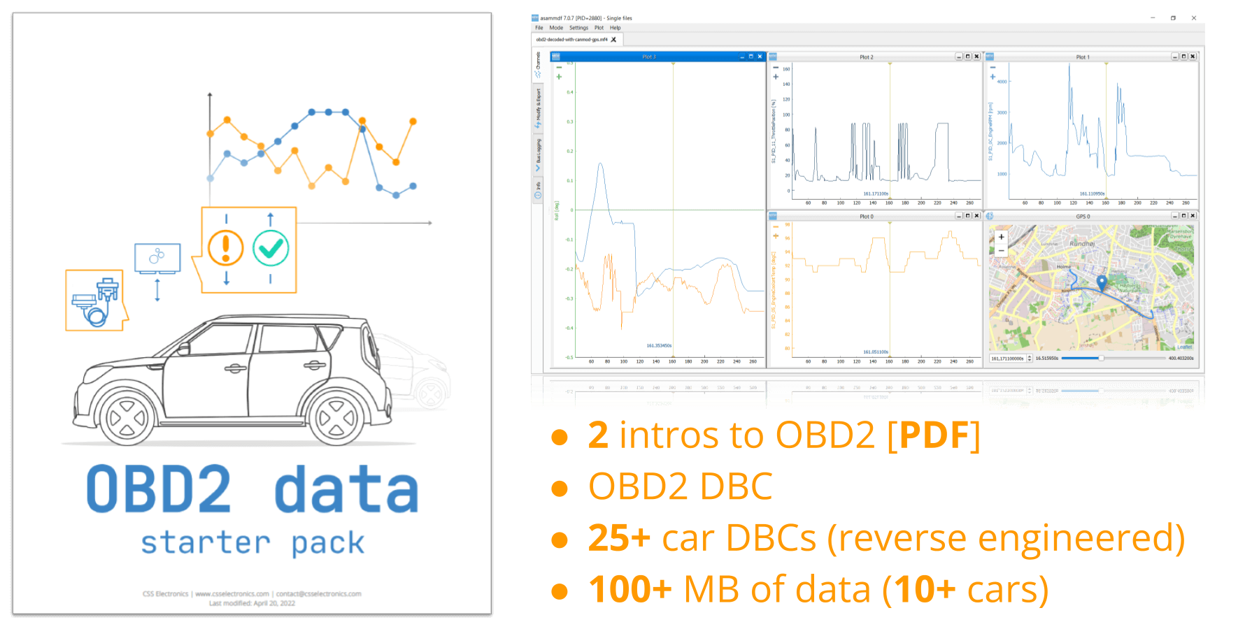
Get the 'OBD2 Data Pack'
Want to try working with real OBD2 data?
Download your 'data pack' including:
- Our OBD2 DBC
- 25+ car DBCs (reverse engineered)
- 100+ MB of data from 10+ cars
This OBD2 PID lookup tool lets you quickly find details for a specific OBD2 PID. The tool will display the available information, as well as how to construct the OBD2 request CAN frame. In addition, the tool provides an example of how the corresponding OBD2 response frame could look - and how the data is decoded to physical values.
OBD2 (On Board Diagnostics) is your vehicles built-in self-diagnostic system - see also our intro to OBD2. It provides a standardized connector and method for interfacing with cars, vans, trucks and other automotive vehicles. For example, it allows your mechanic to use an OBD2 scan tool to diagnose issues in your car when the Malfunction Indicator Light (MIL) indicates a problem.
An important part of OBD2 is the standard SAE J1979, which specifies a range of standard (and public) OBD2 PIDs (Parameter IDs). Basically, tools like OBD2 scanners, OBD2 interfaces, OBD2 data loggers etc. can attempt to send "OBD2 requests" into a vehicle. This is done by connecting the hardware to the vehicle's OBD2 connector (located below the steering wheel) and sending specific CAN bus frames into the vehicle's CAN bus system.
For example, you could request data for the OBD2 PID '0D' (Vehicle Speed) by sending a CAN frame with ID 7DF and the data payload 02 01 0D 55 55 55 55 55. If the vehicle supports this OBD2 parameter, you'll see an "OBD2 response" on the CAN bus with CAN ID 7E8 and a data payload of 03 41 0D XX AA AA AA AA, where 'XX' would reflect the hexadecimal value of the current vehicle speed in km/h.
In this overview, we list all the most commonly used OBD2 parameter IDs in various practical formats.
If you have an OBD2 data logging use case, feel free to contact us for sparring!
Learn more about OBD2 via our videos below:
Programmatic OBD2 PID formats
The OBD2 DBC file can be used in most CAN bus software tools to decode raw CAN frames containing OBD2 PID responses. This is useful if you're e.g. recording data using an OBD2 data logger or OBD2-to-USB interface.
The OBD2 CSV contains similar information as the OBD2 DBC file (and the table overview below), but stored in a CSV-style format. These can be useful if you're looking to e.g. implement your own OBD2 PID decoding from scratch in a script.
If you want to try working with raw OBD2 responses, you can get free sample OBD2 data from our CANedge2. You can e.g. load the MF4 log files in the asammdf GUI - and decode the log files to human-readable form using the OBD2 DBC file.
You can also check out our open source Python API for CAN bus, which lets you load raw log files with CAN/OBD2 data - and decode the data to human-readable form. The API is e.g. used to enable the easy creation of OBD2 telematics dashboards via Grafana.
DBC CSV sample data software tools

OBD2 PID table (service 01)
We created this OBD2 PID table overview as we found other similar tables to be less intuitive (e.g. the OBD-II PID table on Wikipedia). In particular, the table uses a syntax similar to what is used in CAN databases (DBC files). This means that we provide the bit start, bit length, offset and scale factors required for extracting the relevant data bytes from the OBD2 PID response frame.
Specifically, OBD2 uses big endian byte ordering, which means that the extracted byte(s) can be directly translated from hexadecimal to decimal form, referred to as the 'raw_value_decimal' below. The physical value can then be expressed as a linear equation as explained in our DBC intro.
For example, assume we have an OBD2 response data payload for the OBD2 PID 0C (Engine Speed) as follows:
04 41 0C 0A 0C AA AA AA
In this case, the actual signal starts from bit 31 with a length of 16, i.e. the blue bytes above. If we translate the hex string 0A0C to decimal, we get the value 2572. To convert this to Engine Speed we perform the below calculation:
physical_value = offset + scale * raw_value_decimal

       643 rpm = 0 + 0.25 * 2572
This approach can be used across all of the OBD2 PIDs that have a physical unit assigned to them. In contrast, some OBD2 PIDs are 'encoded' and require a PID specific handling - see the Wikipedia OBD2 PID overview for details. Note that the table shows OBD2 PIDs for service 01 (current data), which is the most relevant service for OBD2 data acquisition use cases.
| PID dec | PID hex | Name | Bit start | Bit length | Scale | Offset | Min | Max | Unit |
|---|---|---|---|---|---|---|---|---|
| 0 | 00 | PIDs supported [01 - 20] | 31 | 32 | 1 | 0 | Encoded | |
| 1 | 01 | Monitor status since DTCs cleared | 31 | 32 | 1 | 0 | Encoded | |
| 2 | 02 | Freeze DTC | 31 | 16 | 1 | 0 | Encoded | |
| 3 | 03 | Fuel system status | 31 | 16 | 1 | 0 | Encoded | |
| 4 | 04 | Calculated engine load | 31 | 8 | 1/2.55 | 0 | 0 | 100 | % |
| 5 | 05 | Engine coolant temperature | 31 | 8 | 1 | -40 | -40 | 215 | degC |
| 6 | 06 | Short term fuel trim (bank 1) | 31 | 8 | 1/1.28 | -100 | -100 | 99 | % |
| 7 | 07 | Long term fuel trim (bank 1) | 31 | 8 | 1/1.28 | -100 | -100 | 99 | % |
| 8 | 08 | Short term fuel trim (bank 2) | 31 | 8 | 1/1.28 | -100 | -100 | 99 | % |
| 9 | 09 | Long term fuel trim (bank 2) | 31 | 8 | 1/1.28 | -100 | -100 | 99 | % |
| 10 | 0A | Fuel pressure (gauge pressure) | 31 | 8 | 3 | 0 | 0 | 765 | kPa |
| 11 | 0B | Intake manifold absolute pressure | 31 | 8 | 1 | 0 | 0 | 255 | kPa |
| 12 | 0C | Engine speed | 31 | 16 | 0.25 | 0 | 0 | 16384 | rpm |
| 13 | 0D | Vehicle speed | 31 | 8 | 1 | 0 | 0 | 255 | km/h |
| 14 | 0E | Timing advance | 31 | 8 | 0.5 | -64 | -64 | 64 | deg |
| 15 | 0F | Intake air temperature | 31 | 8 | 1 | -40 | -40 | 215 | degC |
| 16 | 10 | Mass air flow sensor air flow rate | 31 | 16 | 0.01 | 0 | 0 | 655 | grams/sec |
| 17 | 11 | Throttle position | 31 | 8 | 1/2.55 | 0 | 0 | 100 | % |
| 18 | 12 | Commanded secondary air status | 31 | 8 | 1 | 0 | Encoded | |
| 19 | 13 | Oxygen sensors present (2 banks) | ||||||
| 20 | 14 | Oxygen sensor 1 (voltage) | 31 | 8 | 0.005 | 0 | 0 | 1 | volts |
| Oxygen sensor 1 (short term fuel trim) | 39 | 8 | 1/1.28 | -100 | -100 | 99 | % | ||
| 21 | 15 | Oxygen sensor 2 (voltage) | 31 | 8 | 0.005 | 0 | 0 | 1 | volts |
| Oxygen sensor 2 (short term fuel trim) | 39 | 8 | 1/1.28 | -100 | -100 | 99 | % | ||
| 22 | 16 | Oxygen sensor 3 (voltage) | 31 | 8 | 0.005 | 0 | 0 | 1 | volts |
| Oxygen sensor 3 (short term fuel trim) | 39 | 8 | 1/1.28 | -100 | -100 | 99 | % | ||
| 23 | 17 | Oxygen sensor 4 (voltage) | 31 | 8 | 0.005 | 0 | 0 | 1 | volts |
| Oxygen sensor 4 (short term fuel trim) | 39 | 8 | 1/1.28 | -100 | -100 | 99 | % | ||
| 24 | 18 | Oxygen sensor 5 (voltage) | 31 | 8 | 0.005 | 0 | 0 | 1 | volts |
| Oxygen sensor 5 (short term fuel trim) | 39 | 8 | 1/1.28 | -100 | -100 | 99 | % | ||
| 25 | 19 | Oxygen sensor 6 (voltage) | 31 | 8 | 0.005 | 0 | 0 | 1 | volts |
| Oxygen sensor 6 (short term fuel trim) | 39 | 8 | 1/1.28 | -100 | -100 | 99 | % | ||
| 26 | 1A | Oxygen sensor 7 (voltage) | 31 | 8 | 0.005 | 0 | 0 | 1 | volts |
| Oxygen sensor 7 (short term fuel trim) | 39 | 8 | 1/1.28 | -100 | -100 | 99 | % | ||
| 27 | 1B | Oxygen sensor 8 (voltage) | 31 | 8 | 0.005 | 0 | 0 | 1 | volts |
| Oxygen sensor 9 (short term fuel trim) | 39 | 8 | 1/1.28 | -100 | -100 | 99 | % | ||
| 28 | 1C | OBD standards the vehicle conforms to | 31 | 8 | 1 | 0 | Encoded | |
| 29 | 1D | Oxygen sensors present (4 banks) | ||||||
| 30 | 1E | Auxiliary input status | ||||||
| 31 | 1F | Run time since engine start | 31 | 16 | 1 | 0 | 0 | 65535 | seconds |
| 32 | 20 | PIDs supported [21 - 40] | 31 | 32 | 1 | 0 | Encoded | |
| 33 | 21 | Distance traveled with MIL on | 31 | 16 | 1 | 0 | 0 | 65535 | km |
| 34 | 22 | Fuel rail pres. (rel. to manifold vacuum) | 31 | 16 | 0.079 | 0 | 0 | 5177 | kPa |
| 35 | 23 | Fuel rail gauge pres. (diesel, gas inject) | 31 | 16 | 10 | 0 | 0 | 655350 | kPa |
| 36 | 24 | Oxygen sensor 1 (air-fuel equiv. ratio) | 31 | 16 | 1/32768 | 0 | 0 | 2 | ratio |
| Oxygen sensor 1 (voltage) | 47 | 16 | 1/8192 | 0 | 0 | 2 | volts | ||
| 37 | 25 | Oxygen sensor 2 (air-fuel equiv. ratio) | 31 | 16 | 1/32768 | 0 | 0 | 2 | ratio |
| Oxygen sensor 2 (voltage) | 47 | 16 | 1/8192 | 0 | 0 | 8 | volts | ||
| 38 | 26 | Oxygen sensor 3 (air-fuel equiv. ratio) | 31 | 16 | 1/32768 | 0 | 0 | 2 | ratio |
| Oxygen sensor 3 (voltage) | 47 | 16 | 1/8192 | 0 | 0 | 8 | volts | ||
| 39 | 27 | Oxygen sensor 4 (air-fuel equiv. ratio) | 31 | 16 | 1/32768 | 0 | 0 | 2 | ratio |
| Oxygen sensor 4 (voltage) | 47 | 16 | 1/8192 | 0 | 0 | 8 | volts | ||
| 40 | 28 | Oxygen sensor 5 (air-fuel equiv. ratio) | 31 | 16 | 1/32768 | 0 | 0 | 2 | ratio |
| Oxygen sensor 5 (voltage) | 47 | 16 | 1/8192 | 0 | 0 | 8 | volts | ||
| 41 | 29 | Oxygen sensor 6 (air-fuel equiv. ratio) | 31 | 16 | 1/32768 | 0 | 0 | 2 | ratio |
| Oxygen sensor 6 (voltage) | 47 | 16 | 1/8192 | 0 | 0 | 8 | volts | ||
| 42 | 2A | Oxygen sensor 7 (air-fuel equiv. ratio) | 31 | 16 | 1/32768 | 0 | 0 | 2 | ratio |
| Oxygen sensor 7 (voltage) | 47 | 16 | 1/8192 | 0 | 0 | 8 | volts | ||
| 43 | 2B | Oxygen sensor 8 (air-fuel equiv. ratio) | 31 | 16 | 1/32768 | 0 | 0 | 2 | ratio |
| Oxygen sensor 8 (voltage) | 47 | 16 | 1/8192 | 0 | 0 | 8 | volts | ||
| 44 | 2C | Commanded EGR | 31 | 8 | 1/2.55 | 0 | 0 | 100 | % |
| 45 | 2D | EGR Error | 31 | 8 | 1/1.28 | -100 | -100 | 99 | % |
| 46 | 2E | Commanded evaporative purge | 31 | 8 | 1/2.55 | 0 | 0 | 100 | % |
| 47 | 2F | Fuel tank level input | 31 | 8 | 1/2.55 | 0 | 0 | 100 | % |
| 48 | 30 | Warmups since DTCs cleared | 31 | 8 | 1 | 0 | 0 | 255 | count |
| 49 | 31 | Distance traveled since DTCs cleared | 31 | 16 | 1 | 0 | 0 | 65535 | km |
| 50 | 32 | Evap. system vapor pressure | 31 | 16 | 0.25 | 0 | -8192 | 8192 | Pa |
| 51 | 33 | Absolute barometric pressure | 31 | 8 | 1 | 0 | 0 | 255 | kPa |
| 52 | 34 | Oxygen sensor 1 (air-fuel equiv. ratio) | 31 | 16 | 1/32768 | 0 | 0 | 2 | ratio |
| Oxygen sensor 1 (current) | 47 | 16 | 1/256 | -128 | -128 | 128 | mA | ||
| 53 | 35 | Oxygen sensor 2 (air-fuel equiv. ratio) | 31 | 16 | 1/32768 | 0 | 0 | 2 | ratio |
| Oxygen sensor 2 (current) | 47 | 16 | 1/256 | -128 | -128 | 128 | mA | ||
| 54 | 36 | Oxygen sensor 3 (air-fuel equiv. ratio) | 31 | 16 | 1/32768 | 0 | 0 | 2 | ratio |
| Oxygen sensor 3 (current) | 47 | 16 | 1/256 | -128 | -128 | 128 | mA | ||
| 55 | 37 | Oxygen sensor 4 (air-fuel equiv. ratio) | 31 | 16 | 1/32768 | 0 | 0 | 2 | ratio |
| Oxygen sensor 4 (current) | 47 | 16 | 1/256 | -128 | -128 | 128 | mA | ||
| 56 | 38 | Oxygen sensor 5 (air-fuel equiv. ratio) | 31 | 16 | 1/32768 | 0 | 0 | 2 | ratio |
| Oxygen sensor 5 (current) | 47 | 16 | 1/256 | -128 | -128 | 128 | mA | ||
| 57 | 39 | Oxygen sensor 6 (air-fuel equiv. ratio) | 31 | 16 | 1/32768 | 0 | 0 | 2 | ratio |
| Oxygen sensor 6 (current) | 47 | 16 | 1/256 | -128 | -128 | 128 | mA | ||
| 58 | 3A | Oxygen sensor 7 (air-fuel equiv. ratio) | 31 | 16 | 1/32768 | 0 | 0 | 2 | ratio |
| Oxygen sensor 7 (current) | 47 | 16 | 1/256 | -128 | -128 | 128 | mA | ||
| 59 | 3B | Oxygen sensor 8 (air-fuel equiv. ratio) | 31 | 16 | 1/32768 | 0 | 0 | 2 | ratio |
| Oxygen sensor 8 (current) | 47 | 16 | 1/256 | -128 | -128 | 128 | mA | ||
| 60 | 3C | Catalyst temperature (bank 1, sensor 1) | 31 | 16 | 0.1 | -40 | -40 | 6514 | degC |
| 61 | 3D | Catalyst temperature (bank 2, sensor 1) | 31 | 16 | 0.1 | -40 | -40 | 6514 | degC |
| 62 | 3E | Catalyst temperature (bank 1, sensor 2) | 31 | 16 | 0.1 | -40 | -40 | 6514 | degC |
| 63 | 3F | Catalyst temperature (bank 2, sensor 2) | 31 | 16 | 0.1 | -40 | -40 | 6514 | degC |
| 64 | 40 | PIDs supported [41 - 60] | 31 | 32 | 1 | 0 | Encoded | |
| 65 | 41 | Monitor status this drive cycle | 31 | 32 | 1 | 0 | Encoded | |
| 66 | 42 | Control module voltage | 31 | 16 | 0.001 | 0 | 0 | 66 | V |
| 67 | 43 | Absolute load value | 31 | 16 | 1/2.55 | 0 | 0 | 25700 | % |
| 68 | 44 | Commanded air-fuel equiv. ratio | 31 | 16 | 1/32768 | 0 | 0 | 2 | ratio |
| 69 | 45 | Relative throttle position | 31 | 8 | 1/2.55 | 0 | 0 | 100 | % |
| 70 | 46 | Ambient air temperature | 31 | 8 | 1 | -40 | -40 | 215 | degC |
| 71 | 47 | Absolute throttle position B | 31 | 8 | 1/2.55 | 0 | 0 | 100 | % |
| 72 | 48 | Absolute throttle position C | 31 | 8 | 1/2.55 | 0 | 0 | 100 | % |
| 73 | 49 | Accelerator pedal position D | 31 | 8 | 1/2.55 | 0 | 0 | 100 | % |
| 74 | 4A | Accelerator pedal position E | 31 | 8 | 1/2.55 | 0 | 0 | 100 | % |
| 75 | 4B | Accelerator pedal position F | 31 | 8 | 1/2.55 | 0 | 0 | 100 | % |
| 76 | 4C | Commanded throttle actuator | 31 | 8 | 1/2.55 | 0 | 0 | 100 | % |
| 77 | 4D | Time run with MIL on | 31 | 16 | 1 | 0 | 0 | 65535 | minutes |
| 78 | 4E | Time since DTCs cleared | 31 | 16 | 1 | 0 | 0 | 65535 | minutes |
| 79 | 4F | Max fuel-air equiv. ratio | 31 | 8 | 1 | 0 | 0 | 255 | ratio |
| Max oxygen sensor voltage | 39 | 8 | 1 | 0 | 0 | 255 | V | ||
| Max oxygen sensor current | 47 | 8 | 1 | 0 | 0 | 255 | mA | ||
| Max intake manifold absolute pressure | 55 | 8 | 10 | 0 | 0 | 2550 | kPa | ||
| 80 | 50 | Max air flow rate from MAF sensor | 31 | 8 | 10 | 0 | 0 | 2550 | g/s |
| 81 | 51 | Fuel type | 31 | 8 | 1 | 0 | Encoded | |
| 82 | 52 | Ethanol fuel percentage | 31 | 8 | 1/2.55 | 0 | 0 | 100 | % |
| 83 | 53 | Absolute evap system vapor pressure | 31 | 16 | 0.005 | 0 | 0 | 328 | kPa |
| 84 | 54 | Evap system vapor pressure | 31 | 16 | 1 | -32767 | -32767 | 32768 | Pa |
| 85 | 55 | Short term sec. oxygen trim (bank 1) | 31 | 8 | 1/1.28 | -100 | -100 | 99 | % |
| Short term sec. oxygen trim (bank 3) | 39 | 8 | 1/1.28 | -100 | -100 | 99 | % | ||
| 86 | 56 | Long term sec. oxygen trim (bank 1) | 31 | 8 | 1/1.28 | -100 | -100 | 99 | % |
| Long term sec. oxygen trim (bank 3) | 39 | 8 | 1/1.28 | -100 | -100 | 99 | % | ||
| 87 | 57 | Short term sec. oxygen trim (bank 2) | 31 | 8 | 1/1.28 | -100 | -100 | 99 | % |
| Short term sec. oxygen trim (bank 4) | 39 | 8 | 1/1.28 | -100 | -100 | 99 | % | ||
| 88 | 58 | Long term sec. oxygen trim (bank 2) | 31 | 8 | 1/1.28 | -100 | -100 | 99 | % |
| Long term sec. oxygen trim (bank 4) | 39 | 8 | 1/1.28 | -100 | -100 | 99 | % | ||
| 89 | 59 | Fuel rail absolute pressure | 31 | 16 | 10 | 0 | 0 | 655350 | kPa |
| 90 | 5A | Relative accelerator pedal position | 31 | 8 | 1/2.55 | 0 | 0 | 100 | % |
| 91 | 5B | Hybrid battery pack remaining life | 31 | 8 | 1/2.55 | 0 | 0 | 100 | % |
| 92 | 5C | Engine oil temperature | 31 | 8 | 1 | -40 | -40 | 215 | degC |
| 93 | 5D | Fuel injection timing | 31 | 16 | 1/128 | -210 | -210 | 302 | deg |
| 94 | 5E | Engine fuel rate | 31 | 16 | 0.05 | 0 | 0 | 3277 | L/h |
| 95 | 5F | Emission requirements | 31 | 8 | 1 | 0 | Encoded | |
| 96 | 60 | PIDs supported [61 - 80] | 31 | 32 | 1 | 0 | Encoded | |
| 97 | 61 | Demanded engine percent torque | 31 | 8 | 1 | -125 | -125 | 130 | % |
| 98 | 62 | Actual engine percent torque | 31 | 8 | 1 | -125 | -125 | 130 | % |
| 99 | 63 | Engine reference torque | 31 | 16 | 1 | 0 | 0 | 65535 | Nm |
| 100 | 64 | Engine pct. torque (idle) | 31 | 8 | 1 | -125 | -125 | 130 | % |
| Engine pct. torque (engine point 1) | 39 | 8 | 1 | -125 | -125 | 130 | % | ||
| Engine pct. torque (engine point 2) | 47 | 8 | 1 | -125 | -125 | 130 | % | ||
| Engine pct. torque (engine point 3) | 55 | 8 | 1 | -125 | -125 | 130 | % | ||
| Engine pct. torque (engine point 4) | 63 | 8 | 1 | -125 | -125 | 130 | % | ||
| 101 | 65 | Auxiliary input/output supported | 31 | 8 | 1 | 0 | Encoded | |
| 102 | 66 | Mass air flow sensor (A) | 39 | 16 | 1/32 | 0 | 0 | 2048 | grams/sec |
| Mass air flow sensor (B) | 55 | 16 | 1/32 | 0 | 0 | 2048 | grams/sec | ||
| 103 | 67 | Engine coolant temperature (sensor 1) | 39 | 8 | 1 | -40 | -40 | 215 | degC |
| Engine coolant temperature (sensor 2) | 47 | 8 | 1 | -40 | -40 | 215 | degC | ||
| 104 | 68 | Intake air temperature (sensor 1) | 39 | 8 | 1 | -40 | -40 | 215 | degC |
| Intake air temperature (sensor 2) | 47 | 8 | 1 | -40 | -40 | 215 | degC | ||
| 105 | 69 | Commanded EGR and EGR error | ||||||
| 106 | 6A | Com. diesel intake air flow ctr/position | ||||||
| 107 | 6B | Exhaust gas recirculation temperature | ||||||
| 108 | 6C | Com. throttle actuator ctr./position | ||||||
| 109 | 6D | Fuel pressure control system | ||||||
| 110 | 6E | Injection pressure control system | ||||||
| 111 | 6F | Turbocharger compressor inlet pres. | ||||||
| 112 | 70 | Boost pressure control | ||||||
| 113 | 71 | Variable geometry turbo control | ||||||
| 114 | 72 | Wastegate control | ||||||
| 115 | 73 | Exhaust pressure | ||||||
| 116 | 74 | Turbocharger RPM | ||||||
| 117 | 75 | Turbocharger temperature | ||||||
| 118 | 76 | Turbocharger temperature | ||||||
| 119 | 77 | Charge air cooler temperature | ||||||
| 120 | 78 | EGT (bank 1) | ||||||
| 121 | 79 | EGT (bank 2) | ||||||
| 122 | 7A | Diesel particulate filter - diff. pressure | ||||||
| 123 | 7B | Diesel particulate filter | ||||||
| 124 | 7C | Diesel particulate filter - temperature | 31 | 16 | 0.1 | -40 | -40 | 6514 | degC |
| 125 | 7D | NOx NTE control area status | ||||||
| 126 | 7E | PM NTE control area status | ||||||
| 127 | 7F | Engine run time | seconds | |||||
| 128 | 80 | PIDs supported [81 - A0] | 31 | 32 | 1 | 0 | Encoded | |
| 129 | 81 | Engine run time for AECD | ||||||
| 130 | 82 | Engine run time for AECD | ||||||
| 131 | 83 | NOx sensor | ||||||
| 132 | 84 | Manifold surface temperature | ||||||
| 133 | 85 | NOx reagent system | ||||||
| 134 | 86 | Particulate matter sensor | ||||||
| 135 | 87 | Intake manifold absolute pressure | ||||||
| 136 | 88 | SCR induce system | ||||||
| 137 | 89 | Run time for AECD #11-#15 | ||||||
| 138 | 8A | Run time for AECD #16-#20 | ||||||
| 139 | 8B | Diesel aftertreatment | ||||||
| 140 | 8C | O2 sensor (wide range) | ||||||
| 141 | 8D | Throttle position G | 31 | 8 | 1/2.55 | 0 | 0 | 100 | % |
| 142 | 8E | Engine friction percent torque | 31 | 8 | 1 | -125 | -125 | 130 | % |
| 143 | 8F | Particulate matter sensor (bank 1 & 2) | ||||||
| 144 | 90 | WWH-OBD vehicle OBD system Info | hours | |||||
| 145 | 91 | WWH-OBD vehicle OBD system Info | hours | |||||
| 146 | 92 | Fuel system control | ||||||
| 147 | 93 | WWH-OBD counters support | hours | |||||
| 148 | 94 | NOx warning and inducement system | ||||||
| 152 | 98 | EGT sensor | ||||||
| 153 | 99 | EGT sensor | ||||||
| 154 | 9A | Hybrid/EV sys. data, battery, voltage | ||||||
| 155 | 9B | Diesel exhaust fluid sensor data | ||||||
| 156 | 9C | O2 sensor data | ||||||
| 157 | 9D | Engine fuel rate | g/s | |||||
| 158 | 9E | Engine exhaust flow rate | kg/h | |||||
| 159 | 9F | Fuel system percentage use | ||||||
| 160 | A0 | PIDs supported [A1 - C0] | 31 | 32 | 1 | 0 | Encoded | |
| 161 | A1 | NOx sensor corrected data | ppm | |||||
| 162 | A2 | Cylinder fuel rate | 31 | 16 | 1/32 | 0 | 0 | 2048 | mg/stroke |
| 163 | A3 | Evap system vapor pressure | ||||||
| 164 | A4 | Transmission actual gear | 47 | 16 | 0.001 | 0 | 0 | 66 | ratio |
| 165 | A5 | Cmd. diesel exhaust fluid dosing | 39 | 8 | 0.5 | 0 | 0 | 128 | % |
| 166 | A6 | Odometer | 31 | 32 | 0.1 | 0 | 0 | 429496730 | km |
| 167 | A7 | NOx concentration 3, 4 | ||||||
| 168 | A8 | NOx corrected concentration (3, 4) | ||||||
| 192 | C0 | PIDs supported [C1 - E0] | 31 | 32 | 1 | 0 | Encoded |


