EDR: Event Data Recorder - A Simple Intro [UNECE R169]

Need a simple intro to Event Data Recorders (EDR) and UNECE R169?
In this intro we explain the basics of Event Data Recorders for heavy-duty vehicles as per the technical requirements in UNECE R169 and (EU) 2024/2220.
We also explain how the CANedge series of CAN bus data loggers can be used as Event Data Recorders by truck/bus OEMs (Original Equipment Manufacturers).
In this article

What is an Event Data Recorder?
An Event Data Recorder (EDR) is a vehicle blackbox data logger. An EDR records specific data elements (e.g. speed, acceleration, braking) from the vehicle CAN bus before/during/after certain events (e.g. airbag activation) in a format that enables the relevant authorities to conduct crash investigations and safety research, with the goal of improving vehicle safety.
In many cases, the EDR functionality will be embedded within an existing vehicle ECU, typically the airbag control module (ACM), aka Restraint Control Module (RCM). In other cases, the EDR functionality may be retrofitted through a standalone automotive blackbox (e.g. in the form of a CAN bus data logger) or telematics device.

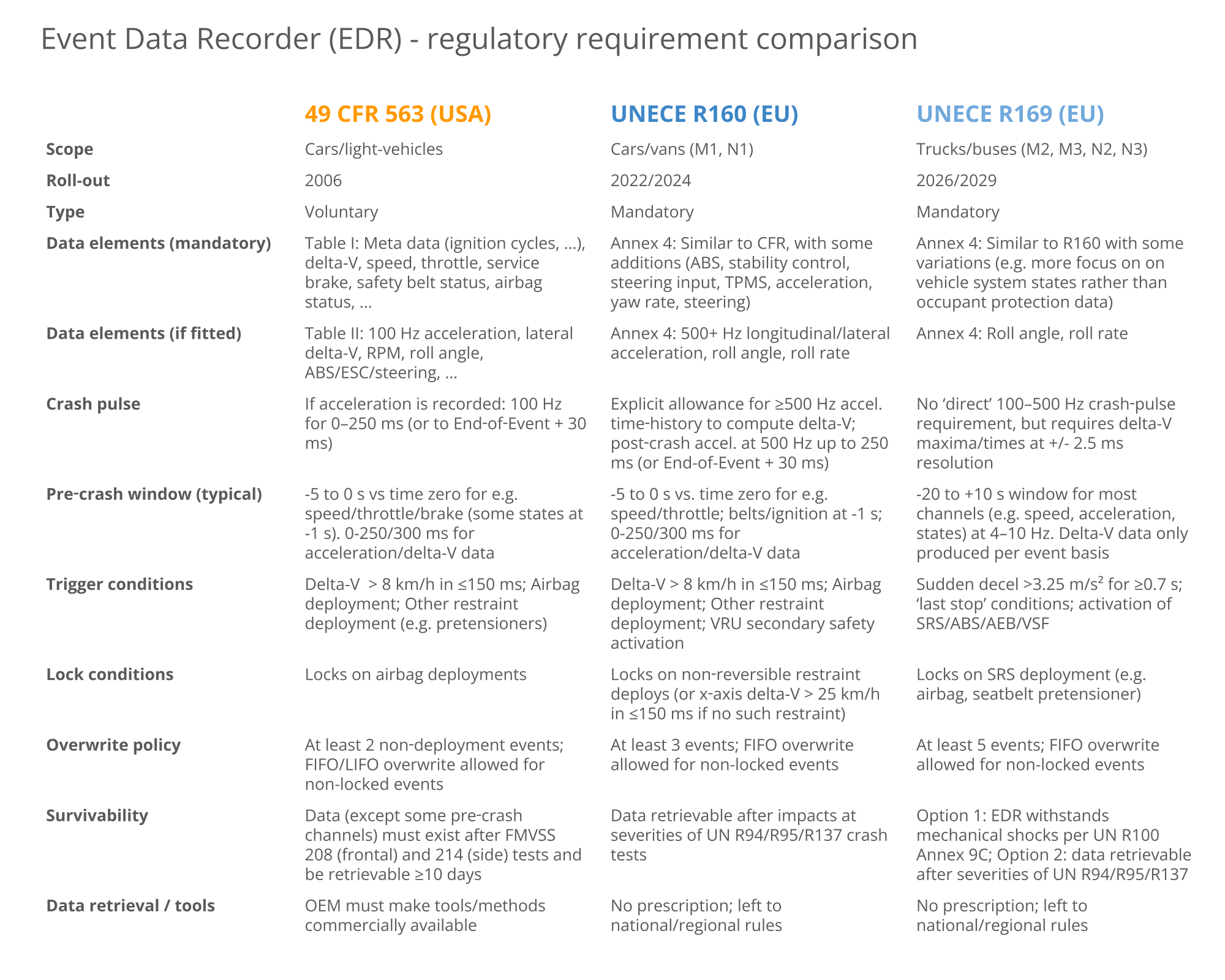
Event Data Recorders are increasingly deployed in both the USA and EU, in part due to the inherent value to both OEMs/authorites - but also due to regulatory requirements. Below we provide a summary of the key regulations that govern EDRs. In this article we focus primarily on R169, but the table below serves as a useful reference for comparison vs. the other key regulations.

What is UNECE R169?
UNECE R169 is an EU regulation that governs the use of Event Data Recorders (EDRs) in heavy-duty vehicles, specifically classes M2, M3, N2, N3 (trucks and buses). In contrast, UNECE R160 governs EDRs in light-duty classes M1, N1 (cars and vans). Both standards are defined by the United Nations Economic Commission for Europe (UNECE) and set out very similar requirements to EDRs.
R169 outlines the minimum requirements for heavy-duty blackbox data loggers, including in particular the below:
- What data must be stored (speed, braking, delta-V, ...)
- What constitutes an event (sudden deceleration, airbags, ...)
- Survivability requirements for the EDR (shock resistance, ...)
EDR history/future
Below is a brief overview of the EDR history and outlook:

- 2004-2006: IEEE 1616 established as the first standard
- 2006: USA specifies what data must be recorded by EDRs in 49 CFR 563
- 2021: R160 adopted by World Forum for Harmonization of Vehicle Regulations
- 2022: EDRs (R160) mandatory in new car/van types (M1, N1) sold in EU
- 2024: EDRs (R160) mandatory in all new car/vans sold in EU
- 2026: EDRs (R169) mandatory in new truck/bus types (M2, M3, N2 N3) sold in EU
- 2029: EDRs (R169) mandatory in all new truck/buses sold in EU
As outlined, Event Data Recorders as per R169 will become mandatory for new heavy-duty vehicle types sold in the EU from January 7, 2026 and in all new heavy-duty vehicles from January 7, 2029.
As per the timeline, the UNECE R160/R169 roll-out mandates an earlier deadline for type approval, meaning that Original Equipment Manufacturers (OEMs) looking to launch a new vehicle type (e.g. a new model) will need to go through the EDR regulatory approval multiple years prior to when they need to need to fit approved EDRs in all newly sold vehicles.
As outlined above, the USA has specified various requirements for EDRs since 2004-2006 as per 49 CFR 563 if they are installed. However, in contrast to the EU, USA does not require the installation of EDRs in cars/trucks, although there are requirements related to Electronic Logging Devices (ELDs) for tracking the hours-of-service in trucks. In part, this was reflected in the National Highway Traffic Safety Administration (NHTSA) ruling in 2006 (as per 49 CFR 563) where it estimated that by 2010 85%+ of vehicles would have EDRs installed through voluntary implementation, thereby avoiding the regulatory requirement for installation.
R169 compliance: Technical EDR requirements
In this section we will outline the key technical requirements for Event Data Recorders as per R169. Specifically, we focus on sections 5.1-5.5 of R169. You can find the full document on the UNECE website.
R169 5.1: Data elements
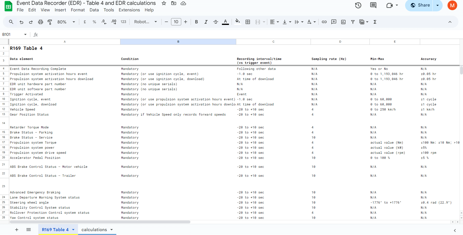
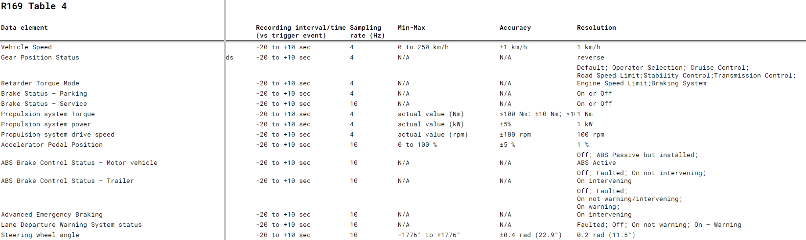
R169 includes an 'Annex 4' table, which lists various parameters that must be recorded in response to certain events. The table includes the recording interval, sampling rate, range, accuracy, resolution and what triggers the data should be recorded in response to.
The 50+ parameters include different categories of signals:
Meta data: A number of parameters reflect meta information, such as event tagging (trigger activated, event recording completed, EDR hardware part number, ignition cycle etc).
CAN data: This includes e.g. speed, gear position, brake status, pedal positions, airbag status, steering wheel angle and more.
CAN/IMU data: This includes e.g. acceleration rates, yaw rates and delta-V (delta velocity) parameters. These may either be produced by existing ECUs in the vehicle or by separate 3D IMUs (Inertial Measurement Units) inside the EDR (or external to it, in e.g. the form of IMU-to-CAN modules).
For a full overview of the R169 EDR data elements, see our Google Sheet version of Annex 4.

Annex 4 vs. CAN signals
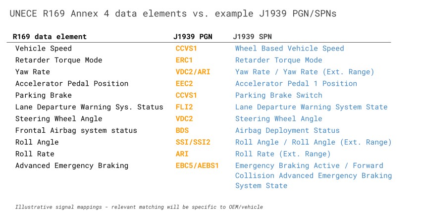
Note that in practice it may differ by vehicle OEM/brand/model how the various CAN based signals are encoded. Typically, multiple signals will be packaged within the same CAN frame. As such, while there are 50+ parameters required, there may in practice be closer to 15-40 CAN frames that must be recorded. It is up to the OEM to identify how each of the requested data elements in Annex 4 can be matched by existing signals on the vehicle CAN bus.
Sometimes a required parameter is matched 1:1 by an existing CAN signal. For example, 'Vehicle Speed' (km/h) can be matched in practically any J1939 heavy-duty vehicle by the signal 'Wheel Based Vehicle Speed' (km/h) from PGN CCVS1 (65265).
However, some of the required parameters are less straightforward.
R169 delta-V explained
For example, the delta-V related parameters are not sampled at a specific rate (4 Hz, 10 Hz), but are instead 'event based'. Further, there is rarely a readily-available signal reflecting this information directly from the CAN bus.
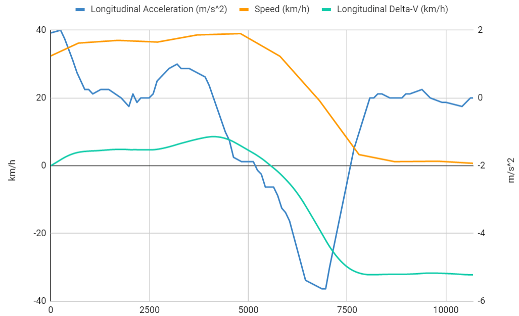
Instead, an EDR would typically need to record longitudinal/lateral acceleration rates (aka X, Y) and then derive the delta-V values based on those underlying signals. While R169 only requires a single observation for each delta-V parameter, it does indirectly require the sampling of a 500+ Hz accelerometer/IMU as explained below.
For example, the parameter 'Time, maximum delta-V, longitudinal' requires an accuracy of +/- 3 ms and a resolution of 2.5 ms. This will in practice require that the EDR is able to sample the longitudinal acceleration rate at 500+ Hz to then derive the max delta-V timing (either via edge-based computation or in post processing). While the 500+ Hz rate is not made explicit in R169, it is made explicit in R160 (and can be derived mathematically from the required accuracy/resolution). It is also worth noting that in R160 it is acceptable for the EDR to not provide delta-V parameters separately as long as the EDR provides the raw longitudinal/lateral acceleration rates at 500+ Hz with sufficient range (+/- 50g), accuracy (+/- 10%) and resolution (1g) - and a similar simplification may be possible in R169 as well, although it is not made explicit. Note also that R169 does specify the mandatory recording of longitudinal/lateral acceleration rates, though at much lower frequency (4 Hz), range (+/- 1.5g) - but higher resolution (0.1g).

Data element exemptions
In practice, some vehicles may not support all the mandatory data elements, in which case the OEM will have to discuss exemptions with the approval authority. Similarly, some specialty vehicles may not support certain trigger information. For example, some military vehicles may not support any of the supplemental restraint system (SRS) trigger signals (airbags, seatbelt pretensioners etc) - and as a consequence these vehicles may gain an exemption from recording some of the mandatory parameters. However, you should always consult the relevant regulatory approval authority for confirmation of this.
R169 5.2: Data format
This section simply specifies that the data elements must be recorded in the format outlined in Annex 4 - i.e. with the outlined time intervals (e.g. -20 to +10 seconds surrounding an event), at certain frequencies (e.g. 4 times per second for Vehicle Speed) and with certain accuracy and resolution.
Note that this does not specify e.g. a concrete file format, structure or software for presenting the data. It also does not dictate how the actual data collection will be performed - e.g. via a CAN diagnostic tool, SD card removal etc. (although data retrieval is detailed in (EU) 2024/2220 Article 4).
R169 5.3: Data capture
This section provides more detailed requirements and we therefore split it into subsections.
A few important points from this section:
- The EDR must capture event data to a non-volatile memory
- Data should be recorded in response to the triggers in section 5.3.1
- The EDR must retain recorded event data until retrieved/overwritten as per 5.3.4
- The EDR must be able to retain at least five different events
In the below we detail each aspect of this.
R169 5.3.1: Conditions for triggering recording of data
This section describes what conditions should apply for the EDR to record a new event.
5.3.1.1: Sudden Deceleration: If the vehicle speed changes at a rate of 3.25+ m/s^2 (0.33+ g) for a period of 0.7+ seconds. This reflects a harsh-braking scenario and is often a good indicator of a crash or near-crash event.
5.3.1.2: Last Stop: This reflects the vehicle stopping under normal conditions, ensuring the EDR captures coherent trip information in addition to crash events. This is triggered if:
- Speed is 0 km/h for 20 s (after being >24 km/h for 6+ s)
- Speed is 0 km/h and the parking brake is applied
- Speed is 0 km/h and the master control switch is deactivated
5.3.1.3: Activation of a safety system: This detects crash / near-crash events using data from the vehicle systems. This event is triggered in the following scenarios:
- Deployment of supplemental restraint systems aka SRS (airbags, seatbelt pre-tensioners, ...)
- Deployment of antilock braking systems (ABS)
- Deployment of emergency brake interventions
- Deployment of vehicle stability controls

The various triggers can be re-formulated in the form of calculations based off various CAN bus signals, although there is a varying degree of complexity in them.
The 5.3.1.1 sudden deceleration trigger can be based off the aforementioned acceleration data required for delta-V calculations. A rolling average can be calculated continuously across the previous 0.7 seconds of data to identify when exactly the average longitudinal acceleration rate exceeds the threshold. This rolling average is easy to calculate during post processing of historical data - though more difficult to conduct in real-time on the EDR itself (edge processing).
The 5.3.1.2 last stop trigger requires a combination of a vehicle speed CAN signal and CAN signals related to the parking brake and master control states. These are all signals that are typically available in standard J1939 heavy-duty vehicles. As with the sudden deceleration, the last stop trigger conditions are trivial to evaluate during post processing if complete trip data is available - but difficult to implement in real-time on the EDR. The 1st sub condition of a 0 km/h speed for 20 seconds requires a rolling average of speed (as with the sudden deceleration) - but the event should only be activated if the speed was previously >24 km/h for 6+ seconds. The 2nd and 3rd sub conditions require that multiple signals are compared across separate CAN messages (with separate time rasters) using 'AND' conditions - which essentially requires that the separate messages are first resampled to a common time raster. In other words, all three sub conditions are quite difficult to implement via edge processing unless a custom script is deployed on the EDR. However, all are simple enough to do in post processing via data extraction tools.
The 5.3.1.3 trigger is the most important one (as we'll see shortly) because the sub condition of 'supplemental restraint system' events must be 'locked' on the EDR (5.3.1.1, 5.3.1.2 and the rest of 5.3.1.3 do not trigger this). Coincidentally, this specific sub condition also happens to be much easier to implement on an EDR via edge processing. This is because the trigger conditions typically break down to multiple evaluations of boolean signal values, e.g. whether the 2-bit J1939 Airbag Deployment Status signal is 0b00 or 0b01 (as an example). Each signal can be evaluated independently with an 'OR' logic between them as the activation of any will imply the event has arisen - which enables simpler trigger signal methodologies to be re-used for this purpose (see also our CANedge discussion for details).
In summary, the most critical trigger to implement 'on edge' on the Event Data Recorder is the 5.3.1.3 trigger - which also happens to be the most feasible to implement. If the other trigger conditions can be evaluated ex post during data retrieval, it greatly simplifies the required functionality on the EDR - enabling much more flexible deployments for OEMs.

R169 5.3.2: Conditions for locking of data
In events where the trigger was a supplemental restraint activation (e.g. airbags), the event data must be 'locked' to prevent it from future overwriting (except if more than 5 locked events arise). As previously explained, if supplemental restraint systems are not available (e.g. in some speciality vehicles), the requirement of locking events may not apply.
R169 5.3.3: Conditions for the establishment of time zero
For each trigger, time zero reflects when the event occurs - e.g. when an airbag is activated. For the 'Last Stop' trigger, time zero reflects the time when the vehicle reaches a speed of 0 km/h.
R169 5.3.4: Overwriting of data
When the EDR memory buffer (e.g. SD card) is full, the device should overwrite the oldest data (first in, first out) - except for 'locked' event data as per 5.3.2. This is subject to implementation strategies decided by the manufacturer and documented to the relevant authorities.
R169 5.3.5: Power & communication failure
Data recorded to the non-volatile memory (e.g. SD card) must be retained after a loss of power. However, it is not a requirement for the EDR to continue recording after the loss of power or communication. In other words, the EDR must be 'power safe'.

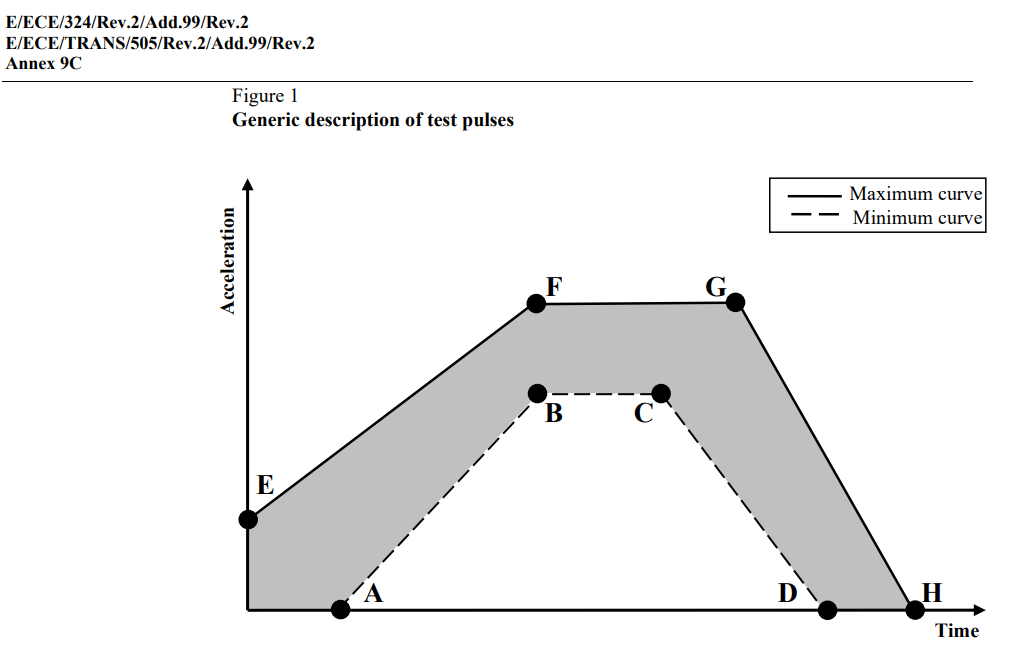
R100 Annex 9C provides detailed test parameters
R169 5.4: Survivability
This section essentially requires that the data must be retrievable even after a crash, which in turn requires that the Event Data Recorder demonstrates survivability. This can be achieved via one of the below options:
Option 1: The EDR must withstand mechanical shocks as per UNECE R100 (Annex 9C). This can e.g. be tested via IEC 60068-2-27 setup to match the 9C requirements.
Option 2: The vehicle manufacturer demonstrates that data is retrievable even after an impact of a specific severity level (R94 Annex 3, R95 Annex 4, R137 Annex 3).
R169 5.5: Deactivation
This section simply specifies that it must not be possible to deactivate the Event Data Recorder. The intention with this section is to state that the EDR should not be possible to deactivate under normal operation of the vehicle e.g. via service tools or similar.
Other EDR requirements as per (EU) 2024/2220
In addition to the requirements of UNECE R169, Event Data Recorders must also satisfy other requirements for deployment by OEMs in heavy-duty vehicles, including in particular those outlined in (EU) 2024/2220 which supplements (EU) 2019/2144 with further technical requirements for EDRs. This supplement includes articles 3, 4, 5 as summarized below:
Article 3: Data Security
This requires that the recorded data is encrypted in a secure manner that also prohibits tampering/modification (as per UNECE R155) - and that the EDR firmware is protected against unauthorized changes.


Article 4: Data Retrieval
The memorandum to R169 states that crash data from Event Data Recorders should be made available via the vehicle OBD2 connector. If this port is no longer functional following a crash, data should be extracted directly from the EDR.
The vehicle manufacturer must provide information on how to access, retrieve and process the event data to the type-approval authority, as well as any interested manufacturer/repairer.
Further, the vehicle/EDR must enable a data extraction tool to produce event reports with information as outlined below:
The event data reports produced by the EDR and/or related data extraction tool must contain the following information:
- The data elements required as per R169
- The host vehicle type, variant and version
In addition, the below requirements are specified:
- Data must not be extractable without unlocking the vehicle
- Data must be available in a machine-readable format
- The data must anonymous (not linked to a person)
In regads to the host vehicle details, this section of the memorandum also states that the manufacturer must demonstrate that the vehicle specific information must be available after a crash as per R169 section 5.4.1. In practice, the required information corresponds roughly to the Vehicle Identification Number, which can be extracted using CAN bus communication if this functionality has survived a crash. The VIN must not be recorded by the EDR during event logging and active operation as it can be linked to the driver - thus de-anonymizing the data. Some EDR data extraction tools simply allow for entering the VIN manually.
Article 5: Roadworthiness testing
This adds two additional requirements for EDRs:
- It must be possible to verify the correct operational status of the EDR by visually inspecting the 'failure warning signal status' of the vehicle's instrument cluster dashboard
- It must be possible to determine the EDR operational status and software integrity using electronic vehicle interface, i.e. via CAN bus communication using the OBD2 connector


Automotive EMC (UNECE R10)
While EMC requirements are not explicitly stated in R169 or the related memorandum, UNECE R10 (aka automotive EMC) is generally a requirement for electronic devices deployed in on-road production vehicles. This regulation ensures that EDRs can be safely used in automotive deployments:
- The EDR must satisfy strict emission limits
- It must pass various immunity, ESD and supply transient tests
UNECE R10 is required for electronic devices deployed in vehicles, so as to enable automotive-type approvals. In other words, this goes beyond regular CE-marking of electronics.
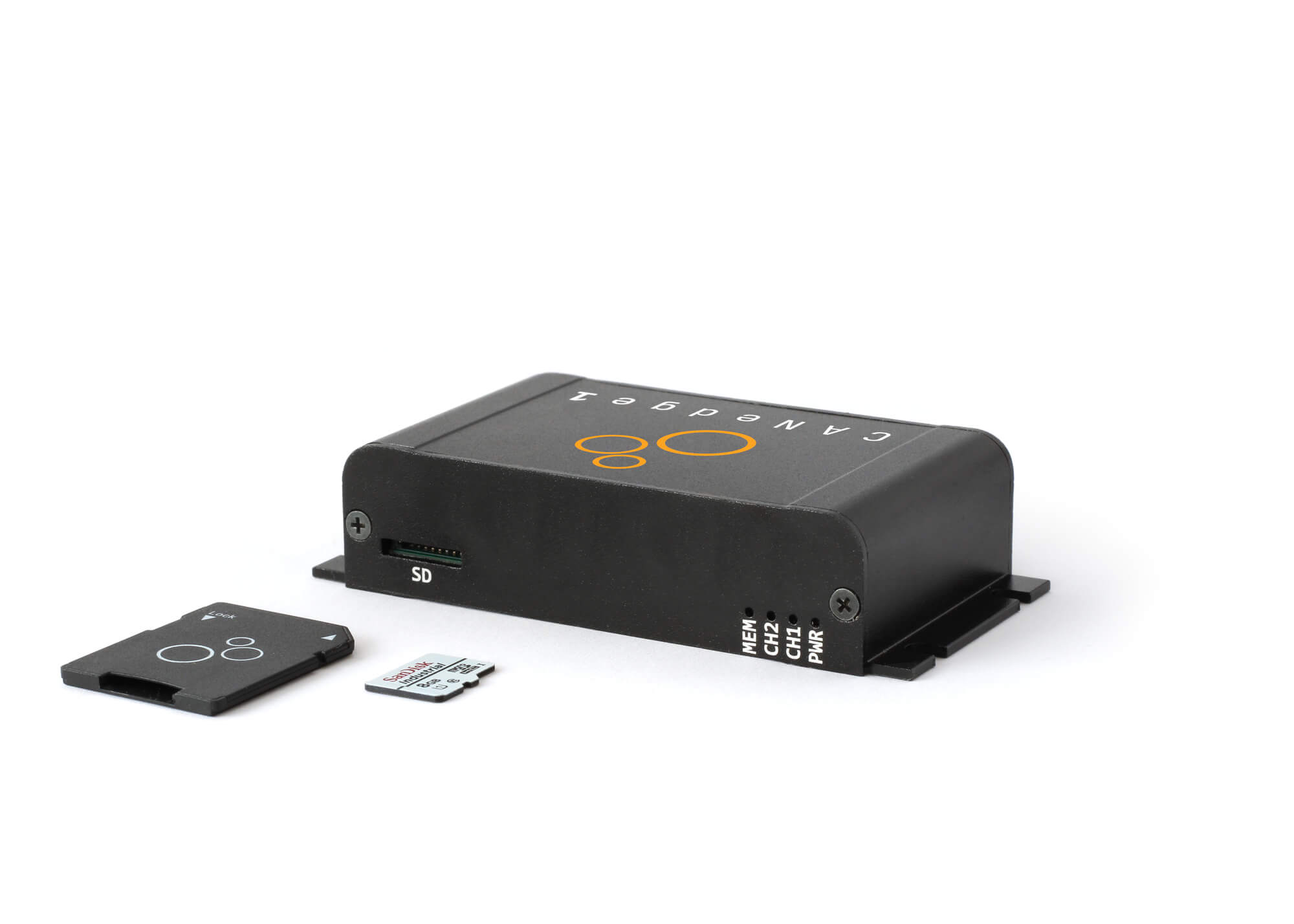
Using the CANedge as an Event Data Recorder (EDR)
The CANedge is a 2 x CAN/LIN data logger with optional GPS, WiFi and LTE. The device is popular amongst e.g. OEM engineers who use it in e.g. testing, diagnostics, R&D, telematics. In addition, it is frequently used as a heavy-duty vehicle blackbox data logger - see e.g. our 100+ case studies.
In this section we explain how the device can serve as a low cost Event Data Recorder as per UNECE R169 by going through each of the technical EDR requirements.

Cyclic logging vs. event logging
Importantly, the CANedge conceptually differs from most Event Data Recorders as it will not attempt to log data only during events. Rather, it can be configured to record a rolling window of historical data (e.g. the last 6 months of data) - and a small data extraction software tool can be created to download the full dataset from the SD card, decode it, analyze it and present the required EDR data elements in the required format.
In the following sections we go through the CANedge compliance vs. each of the R169 requirements.
While R169 assumes event-triggered capture, the regulation is performance-based - it defines the data to be retained, not the recording mechanism. The CANedge achieves functional equivalence by continuously buffering the required data and using post-processing software to identify, format and present the event records.
The cyclic logging approach has multiple benefits:
- It provides full-trip context on any events (for diagnostics/liability analysis)
- It eliminates the risk of 'missed events' related to e.g. threshold calibration errors
- It drastically simplifies integration for vehicle OEMs
R169 5.1: Data elements
The CANedge lets you log any raw CAN bus data via the 2 x CAN channels. For the ECU and IMU related data, this implies that the CANedge will be able to record the required CAN-based data as long as it is made available to the device as raw CAN frames via one or two CAN channels. The R169 5.1 meta data can be derived indirectly from the recorded CAN bus data (e.g. using propulsion system activation hours), along with contextual information from the CANedge (e.g. device HW/SW revision).
The CAN/IMU data like acceleration rates (and the derived delta-V data) is a bit more complex, as explained previously. Typically the delta-V data is not directly produced by an existing CAN node. Instead, a more common solution will be to use the CANedge to record acceleration data (longitudinal, lateral) in a suitable format at sufficient frequency (500+ Hz) so as to allow for subsequent calculation of the delta-V event data based on these rates. If no existing vehicle ECU exposes this data via CAN, an external IMU-to-CAN module can be connected to the CANedge CAN2 channel to enable the recording of this data along with the vehicle data from CAN1.
Note that in the US-based 49 CFR 563 regulation, a 100 Hz IMU suffices to produce the required raw acceleration rates (and thus the basis for the delta-V requirements). If your goal is to deploy the CANedge is an EDR for US-based vehicles, a firmware update can enable the internal CANedge incl. GPS/IMU to produce the required 100 Hz output rate. However, R160 explicitly requires that the acceleration data is recorded at 500+ Hz, while R169 indirectly requires this in order to satisfy the data format requirements (e.g. +/- 2.5 ms resolution on the delta-V time).
As explained previously, approval authorities may accept that the EDR simply provides access to the raw longitudinal/lateral acceleration data, assuming it is in a suitable format that will allow for extracting the required delta-V information. But alternatively, the data extraction tool can be set up to perform the relevant calculations based on the acceleration data in order to directly report the delta-V values and timings.
In some use cases the required data elements may be split across more than two CAN buses. In this case you can combine the CANedge with our CANmod.router, allowing a single CANedge to record 5 x CAN channels into a single log file.

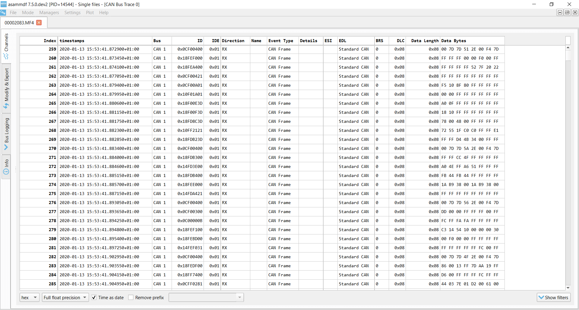 The CANedge records raw CAN frames with configurable filters/prescalers
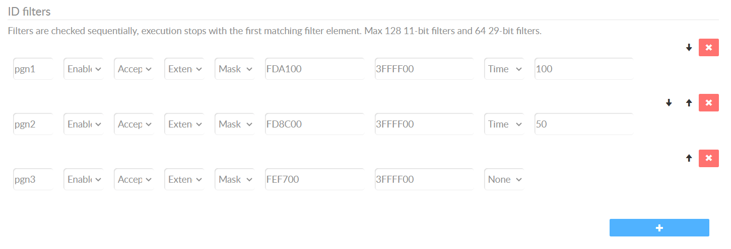 Easily filter which PGNs to record (and at what frequency)
R169 5.2: Data format
The CANedge can record all the required signals assuming they are available from the connected CAN buses (incl. optionally from external IMU-to-CAN modules). The vehicle OEM must ensure that the required signals are made available at the required frequency, accuracy and resolution outlined in R169 Table 4. If needed, the CANedge can be configured with CAN ID filters/prescalers to selectively reduce the frequency of various messages to the sampling rates described in Annex 4 - thus conserving space.
The CANedge will record the raw CAN bus data into a standardized binary log file format (MDF), which is supported by a number of free software/API tools. These tools include e.g. the asammdf GUI for ad hoc analysis, Python/MATLAB and dashboard visualization tools. These tools are helpful in generally understanding the historical data recorded by the CANedge (incl. beyond the regulatory event data).
When event data is to be analyzed by authorities (e.g. following a crash event) a small data extraction tool (e.g. based on the CANedge Python API) can be used to download the data from the SD card, decode it and extract the relevant event information for presentation in the required format. This also means that any derived signals (e.g. meta data, delta-V, ...) can be extracted as part of this post processing step.
This software application can be developed quickly by leveraging the existing software/API tools available for the CANedge - and at CSS we can help OEMs in the development process.
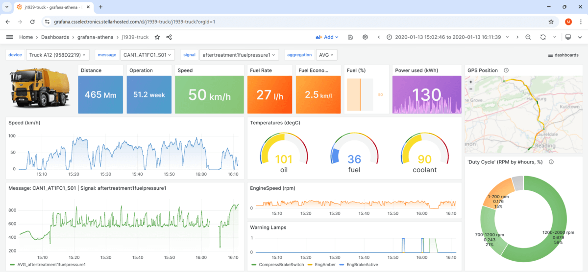 Data can be decoded and presented in dashboards, PDFs, CSV
outputs, ...
Data can be decoded and presented in dashboards, PDFs, CSV
outputs, ...
Simple-to-use Python APIs let you create custom data extraction tools easily
R169 5.3: Data capture
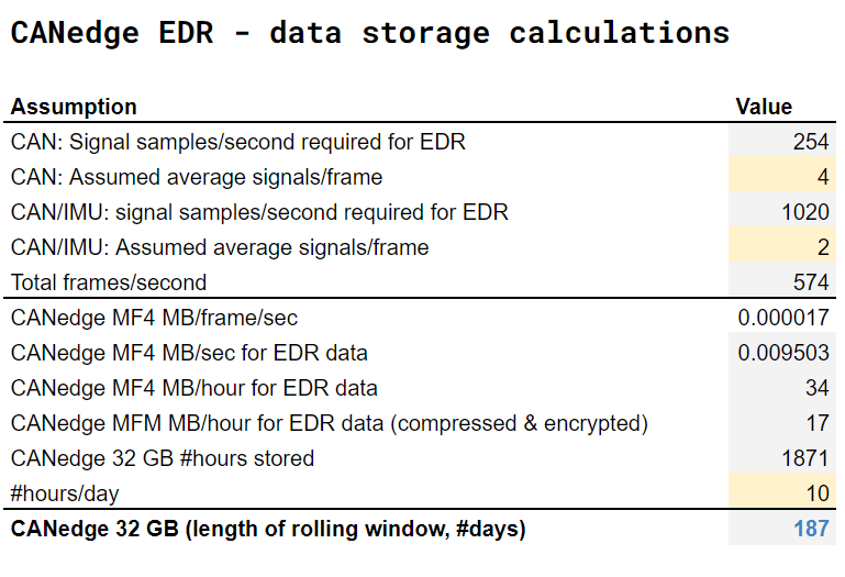 Our Annex
4 overview includes CANedge EDR cyclic storage estimates
Our Annex
4 overview includes CANedge EDR cyclic storage estimates
R169 5.3.1: Conditions for triggering recording of data
R169 generally assumes that an Event Data Recorder will record data only surrounding the outlined events (with some data being recorded e.g. 20 seconds before and 10 seconds after 'time zero' of the event). As explained in the start of this section, the CANedge works differently.
Specifically, the CANedge can be set up to record a rolling window of data that includes the required data elements at the required frequency (via CAN ID filters/prescalers). If you use e.g. a CANedge1 (32 GB), this will typically allow the device to record a rolling window of 6+ months of EDR data - thus recording data regardless of whether events arise or not. This incorporates an assumption that the CANedge has to record an IMU-frame with acceleration data at 500 Hz on top of the other EDR data elements (for the subsequent calculation of delta-V related data).
A light-weight data extraction tool can be made (in collaboration with our team) to identify the events and extract the required data surrounding these events in the required format.
Of course, end consumers of the event data (e.g. crash investigators) will only see the relevant event data presented in the required format (e.g. PDF reports) - as the extraction is handled during the data download process from the SD card.
In practice, this approach requires that all of the required data parameters are available from the vehicle's CAN bus. Further, in order for the 32 GB SD card to store a sufficiently long time period (e.g. >6 months), the CANedge should be configured so as to only record the required CAN frames at the required frequency (e.g. 4 Hz, 10 Hz).

R169 5.3.2: Conditions for locking of data
The CANedge will by default overwrite the oldest data on the SD card if the device runs out of space. However, the overwriting only occurs if the vehicle is in active operation for longer than the cyclic window (e.g. 6+ months) after the event. This will in practice ensure that there is ample time to retrieve event data of interest for e.g. crash investigation purposes.
In some cases, this behavior may suffice for EDR approval. For example, if the vehicle has no supplemental restraint systems (SRS), the trigger logic related to the SRS signals would not apply - and therefore there would be no requirement of 'locking' any event data. Further, some approval authorites may also accept this methodology in general as long as it is clearly documented.
 The CANedge could be modified to enable ring-buffer / event-locking
However, in some cases the approval authorities may require that the CANedge is able to 'lock' event data from being overwritten. Because of this, we are looking into potentially implementing support for 'event locking' in an upcoming CANedge firmware update.
We are working with OEMs that are interested in using the CANedge as their Event Data Recorder (EDR). Depending on the exact requirements from the type approval authorities, it may be necessary to implement a firmware update to the CANedge to enable a more formalized 'locking' of event data.
Currently, the CANedge is able to start/stop logging based on a 'control signal' aka trigger. This could e.g. be the activation of an airbag. This functionality can be extended to support multiple trigger signals so as to support multiple SRS type triggers (e.g. airbags, seatbelt tensioners, ...), with an 'OR' condition stating that if either of these triggers become active, the control signal 'start condition' is considered to be met.
Further, the control signal functionality could be extended to support an 'event lock' mode where the device generally records data as normal - but when a start signal is triggered, the device will change the previous, current and subsequent log files to 'read-only' (until the next power cycle or until the stop signal condition is met). The implication of this would be that the CANedge 'cyclic logging' functionality would 'skip' the read-only files, effectively guaranteeing that these are locked and not overwritten.
Importantly, new data will only be recorded by the CANedge if the vehicle is operational (and thus actively broadcasting CAN bus data). As such, if the vehicle is e.g. non-operational for a long period following a crash, the device will not record further data and therefore none of the historical event data will be overwritten. In practice, this implies that for all practical intents and purposes, event data is going to be retained for a sufficient amount of time so as to ensure it can be analyzed in the case crash investigations have to be conducted for the vehicle.
"event_name": "AirbagActivation",
"messages_match_type": "contains",
"messages_filtered_list": "CAN1_BDS",
"trigger_signals": ["AirbagDeploymentStatus"],
"lower_threshold": 0,
"upper_threshold": 1,
"rising_as_start": True,
"exact_match": False,
"raster" : ""
}
R169 5.3.3: Conditions for the establishment of time zero
The CANedge hardware itself will not attempt to determine event timings (except if 'event locking' is required and introduced) and therefore it will not directly produce any of the event-related meta data. Instead, the data extraction tool can be made to extract the data, identify events and produce the required data elements. This software tool will thus be able to identify time zero for any events in the data as per the methodology outlined in R169, as long as the relevant CAN signals are part of the data recorded by the CANedge. Similar functionality is already used by many CANedge users for general event detection workflows.
R169 5.3.4: Overwriting of data
As outlined in 5.3.2, the CANedge will by default overwrite the oldest data when the SD card gets full. This is in line with 5.3.4, except that locked data should not be overwritten. See the previous section for comments on locked event data.
R169 5.3.5: Power & communication failure
The CANedge is designed to be 100% power safe. This is achieved via a super capacitor inside the device, which retains power sufficiently long to enable the device to safely close down the current log file it is recording - without experiencing data loss or SD card corruption.

 The CANedge can optionally be installed in our IP67 enclosure
R169 5.4: Survivability
The CANedge is designed to be extremely robust and is deployed across 10,000+ companies in 100+ countries, including extensively in heavy-duty applications - see also our 100+ case studies. The device is not yet tested as per UNECE R100 Annex 9C, but this is something that can be arranged as part of an EDR evaluation project.
For use cases that require a more rugged enclosure, you can deploy the CANedge with the tailor-made IP67 enclosure, enabling a low cost, compact and plug & play solution for making the device 100% dust-tight and waterproof.
R169 5.5: Deactivation
The CANedge remains actively logging as long as it is powered.
(EU) 2024/2220 Article 3: Data Security
In our CANedge security intro we explain how the CANedge enables secure CAN bus data logging. This includes in particular the ability to enable data encryption using an AES-GCM algorithm, which also includes authenticity checks, which guarantee that the data cannot be tampered with. The data encryption password itself can be encrypted as part of the device Configuration File. Further, the CANedge uses digitally signed firmware files, thus ensuring that unauthorized modification of the device firmware is not possible.

(EU) 2024/2220 Article 4: Data Retrieval
The CANedge data can be retrieved simply by extracting the micro SD card from the device. The device does not support extracting the data via CAN, e.g. via the OBD2 connector.
We recommend checking with the relevant approval authority if they consider it acceptable that data extraction is always performed via SD card removal and not via CAN.
(EU) 2024/2220 Article 5: Provisions for roadworthiness testing
The CANedge can transmit custom CAN frames onto the CAN bus (e.g. to mimic a specific J1939 message) and/or CAN heartbeat message to showcase that the device is operational, which can be displayed visually to an operator/technician - as well as read by a CAN bus interface. Further, the device LEDs can be used to visually inspect if the device is powered on and recording data to the SD card.
In many use cases, the integrator OEM sets up a visual display (e.g. via the instrument cluster dashboard) to provide a warning lamp signal if the CAN heartbeat is not received from the CANedge at the expected rate (default 1 Hz), thus enabling visual inspection. The CAN heartbeat message can of course also be recorded via any CAN bus interface to confirm the integrity of the CANedge.
If an existing instrument cluster display is to be used, it may require that the CANedge transmits e.g. J1939-73 compatible messages in order to communicate its status. Depending on the detailed implementation requirements, this may be possible in the current functionality of the device, or it may require a firmware modification.

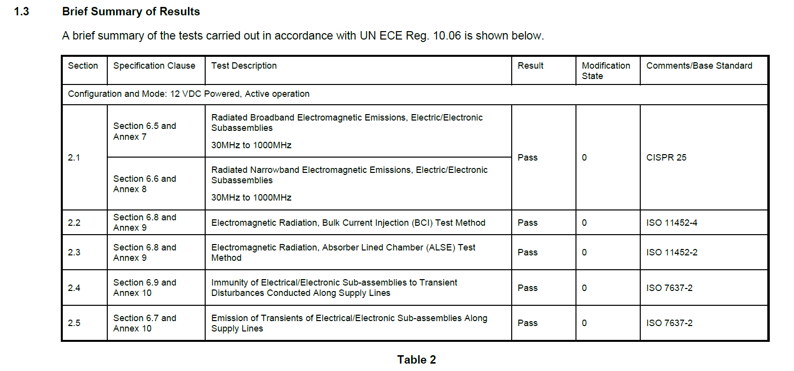
Automotive EMC (UNECE R10)
The CANedge series (CANedge1, CANedge2, CANedge3) has passed ECE R10 testing (conducted by TÜV SÜD) as per CISPR 25, ISO 11452-4, ISO 11452-2 and ISO 7637-2 standards.
Which CANedge device?
In summary, the CANedge is a great option if you need an Event Data Recorder for your heavy-duty vehicles as per R169, (EU) 2024/2220 and R10 requirements.
By using the CANedge, you will be able to solve your regulatory EDR requirements, while also gaining access to critical historical insights beyond the limited time periods surrounding the specified events as per R169. You essentially always have access to a substantial historical window of data - enabling you to not only investigate crash events, but also e.g. capture intermittent issues to help service end customers and speed up diagnostics.
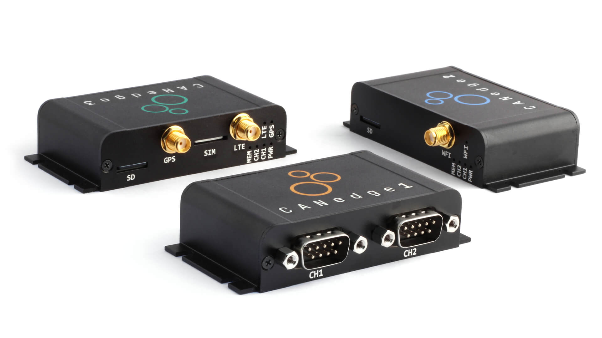
For most use cases, you can go with our CANedge1 as it will allow you to log 2 x CAN/LIN channels to the SD card.
As explained you may need to add an external IMU-to-CAN module with 500+ Hz output rate if such data is not already available from your vehicle CAN bus. If your EDR use case requires a lower frequency IMU output (5-100 Hz), the CANedge1 incl. GPS/IMU may also be an option as outlined.
If you wish to offload the data to your own server, you can use the CANedge2 (with WiFi) or CANedge3 (with LTE). Connected CANedge devices rae ideal if you want to both deploy telematics, while solving your EDR requirements.
If you are interested in using the CANedge as your Event Data Recorder, contact us for 100% free technical sparring.
Want to learn more about using the CANedge as an EDR?
Get your CANedge today - and contact us for sparring!


