A2L File Explained (XCP on CAN) - A Simple Intro [2026]

Need a simple intro to the A2L file format? (aka ASAP2 or ASAM MCD-2 MC)
In this tutorial we explain the A2L file with a focus on data acquisition via XCP on CAN. Specifically, we cover the basics, file syntax, editor tools - and the link to DBC files.
To get practical, we also showcase our 'canedge-xcp' Python tool that lets you initialize XCP DAQ lists for the measurements you wish to record based on your A2L file.
Learn more below!
In this article

What is an A2L file?
The A2L (ASAP2) is a standardized text file format defined in the ASAM MCD-2 MC standard. An A2L file describes the internal data of an ECU - and how a master tool can communicate with it for the purpose of measurement and calibration.
The first version of ASAM MCD-2 MC was released June 15 1999 (1.3.1), while the latest version was released Jan 30 2018 (1.7.1). The standard is maintained by ASAM (Association for Standardization of Automation and Measuring Systems).
In practice, A2L files are primarily used with CCP (CAN Calibration Protocol) or XCP (Universal Measurement and Calibration Protocol). CCP is limited to using CAN as the lower layer protocol, while XCP can be based on e.g. CAN, Ethernet, FlexRay, SxL.
A2L files offer vast flexibility, but can also be huge and complex. As such, we limit the scope of this tutorial to focus on A2L files in the context of data acquisition via XCP on CAN.

A2L file syntax
In practice, you will use an editor tool to load/create/edit/export an A2L file. This helps ensure valid syntax and avoid errors.
However, to properly understand A2L files it is useful to review the raw file syntax. In this section we outline the most relevant sections of the slim A2L file from our canedge-ccp-xcp github page.
General syntax explanation
The A2L file format uses an ASCII-format and supports UTF-8/16/32 encoding. The files consist of keywords, parameters, delimiters and comments.
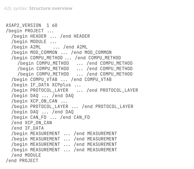
A keyword may contain parameter values (e.g. the keyword 'ASAP2_VERSION' containing the value '1 60') - and it may contain other keywords. This also means that we refer to entire 'sections' of the A2L file as specific keywords like PROJECT, HEADER, MEASUREMENT etc. Such sections may be enclosed by '/begin' and '/end' delimiters for ease of interpretation.
In the illustration we show the top-level raw structure of our sample A2L file. This overview is useful in keeping track of the file as we deep dive on individual sections below.
1: A2L header and general details
The A2L file contains header info, details on the structure of various sections and general parameters.
1.1: A2L PROJECT, HEADER and MODULE
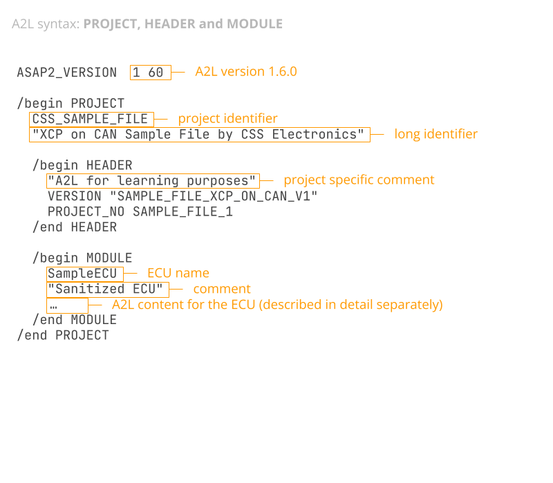
Every A2L file only contains a single PROJECT keyword, which includes a project identifier parameter and optionally a longer identifier as a string. Within the PROJECT keyword the HEADER contains info like the project number and ECU software version. Further, the PROJECT keyword contains one or more MODULE keywords, each reflecting a single ECU - though in practice A2L files only include a single MODULE. The MODULE keyword contains all of the actual ECU description details - including the other sections described below. All of these keywords are referred to as 'top-level keywords'.
Note: While technically not part of the PROJECT keyword, the A2L must also contain the ASAP2_VERSION keyword to specify the version of the standard used. It may also contain an A2ML_VERSION to specify the version of the A2L meta language (AML) used.
1.2: A2L A2ML
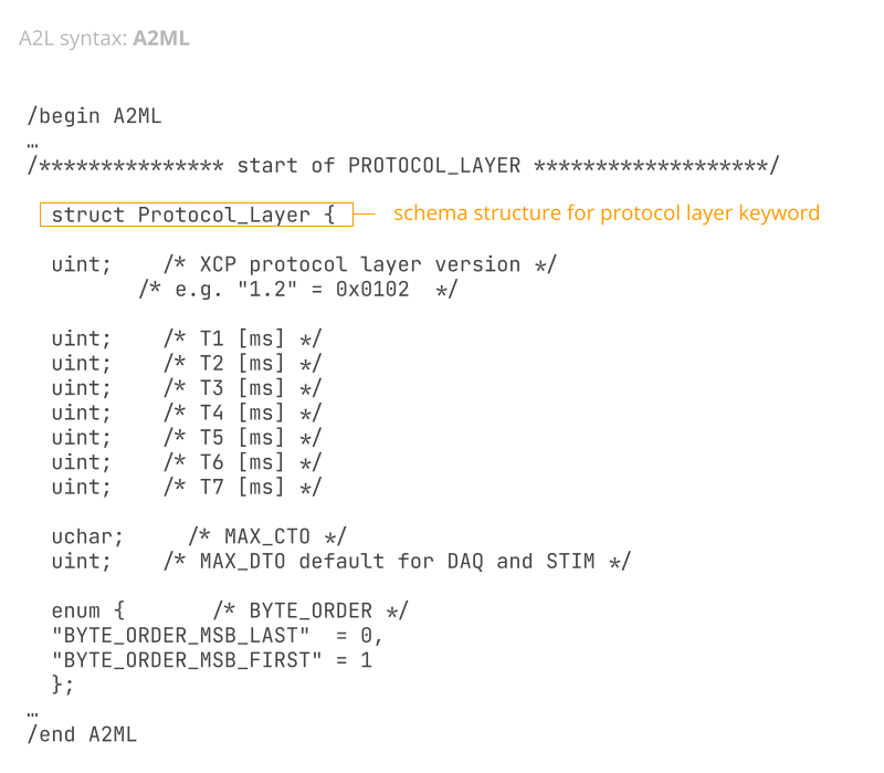
Within the MODULE keyword, the A2ML keyword describes the syntax/structure of another A2L section called IF_DATA (more below). This can be compared to the JSON Schema concept used by the CANedge for handling JSON configuration files: Here, a JSON 'Rule Schema' describes the configuration file structure, field syntax and value restrictions - while the JSON 'Configuration File' contains the actual parameter values. As an example, the A2ML section describes the structure of the PROTOCOL_LAYER, DAQ and XCP_ON_CAN sections found in IF_DATA. If your goal is to simply 'read' specific parameter values from an A2L, the A2ML section can largely be ignored.
1.3: A2L MOD_COMMON
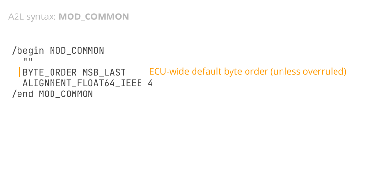
This provides 'default parameter values' for the MODULE aka ECU as a whole. For example, it may specify the byte order to be used. However, the values provided here are overruled if the same parameter is specified within a nested keyword.
2: A2L measurements and conversion methods
A core part of the A2L file is the description of internal ECU measurements (aka signals) and their decoding rules.
2.1: A2L MEASUREMENT
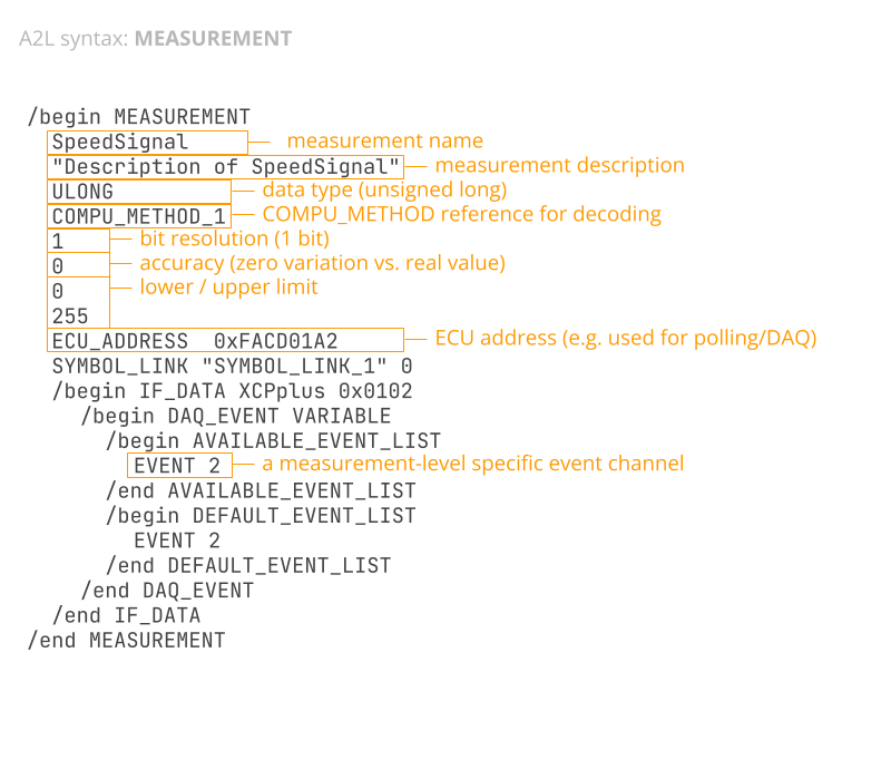
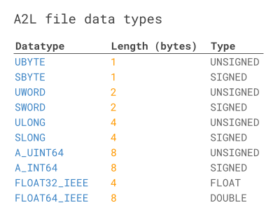
This keyword describes a specific ECU measurement (aka variable/signal) that can be recorded. Examples may include RPM, speed, temperatures etc. Each MEASUREMENT keyword contains a name, description, data type (e.g. UBYTE for unsigned byte) and a reference to a specific COMPU_METHOD that details how to convert the raw data for this measurement into human-readable form.
Next, the keyword contains the bit-resolution (typically 1), accuracy (typically 0, reflecting zero variation vs. real value), lower/upper limits and the ECU address. As explained in our intro to XCP on CAN, the ECU address is used by the master tool to e.g. request data from the ECU on specific measurements. The MEASUREMENT may sometimes contain an ECU_ADDRESS_EXTENSION as well.
Note that the measurement data type information indirectly provides details on the signage and data length. This information is relevant when it comes to logging/decoding data (more on this later). See the mapping table.
A measurement may include several other optional keywords. These are often used to provide additional information about the measurement or to overrule certain properties at the measurement level (e.g. BYTE_ORDER). It is even possible to include an IF_DATA section to overrule certain interface-specific properties, such as what event lists a measurement may be assigned to.
2.2: A2L COMPU_METHOD
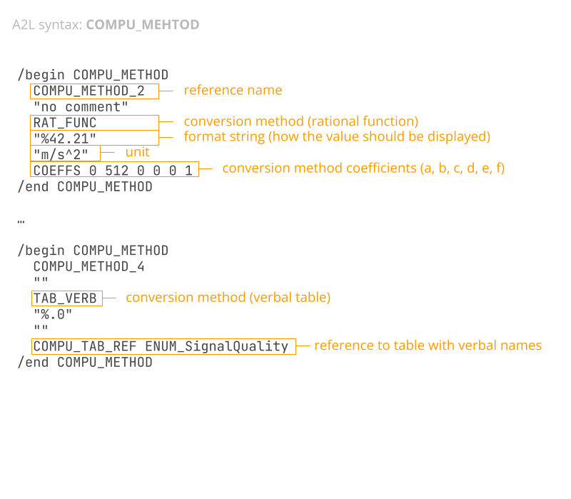
The MODULE may contain multiple COMPU_METHOD keywords. These contain decoding rules that allow raw data (e.g. raw CAN bus data bytes) to be decoded into human-readable form aka physical values. The decoding rules can be referenced by one or more measurements/signals by referring to the 'name' of the COMPU_METHOD (e.g. COMPU_METHOD_2).
The keyword specifies one of the below conversion methods:
- LINEAR: Linear function with scale and offset (similar to DBC)
- IDENTICAL: No conversion (i.e. scale of 1, offset of 0 in DBC)
- RAT_FUNC: Rational function with 6 coefficients (more below)
- TAB_NOINTP: Conversion table (without interpolation)
- TAB_INTP: Conversion table (with interpolation)
- TAB_VERB: Conversion table (with verbal names)
- FORM: Formula (for custom decoding logic)
Depending on the method, the COMPU_METHOD may also contain the relevant coefficient values. In COMPU_METHOD_2, the method used is RAT_FUNC, which involves 6 coefficients (a, b, c, d, e, f) which in this case equal 0 512 0 0 0 1.
To better understand the conversion logic, consider below example formulas:
LINEAR: phy = a*raw + b
RAT_FUNC: raw = (a*phy^2 + b*phy + c)/(d*phy^2 + e*phy + f)
As evident, the conversion methods define the physical value as a function of the raw value, except for RAT_FUNC, which does the inverse. However, in 99% of cases the RAT_FUNC coefficients a, d, e equal 0, meaning the function simplifies as below:
In this case the RAT_FUNC is equivalent to the LINEAR method. Note that the COMPU_METHOD also provides the unit and formatting for the measurement.
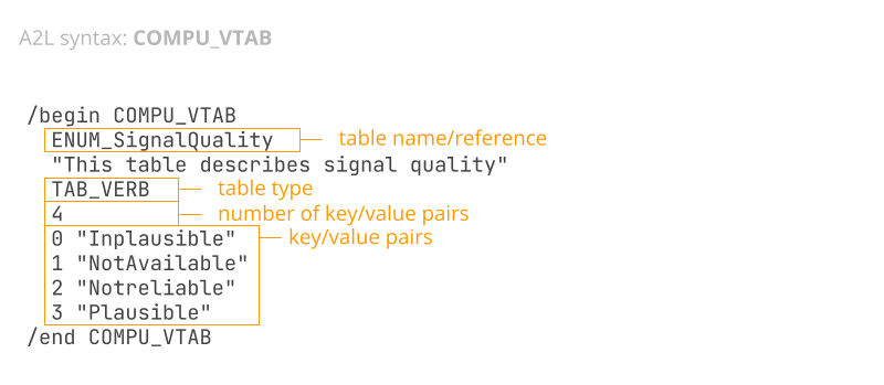
2.3: A2L COMPU_VTAB
As evident from the COMPU_METHOD keyword, one of the listed conversion methods is TAB_VERB, which allows for mapping values to verbal names. When this is used, the COMPU_METHOD contains a reference to such a mapping table, with the actual table described in a COMPU_VTAB section. This is very similar to value tables in DBC files. In the example shown, the COMPU_VTAB has the name ENUM_SignalQuality with a description and the number of key/value pairs (in this case 4). This is followed by the actual key/value pairs. A similar concept exists for e.g. the TAB_NOINTP conversion method where a COMPU_TAB keyword describes the mapping table.
3: A2L interfacing/communication details (IF_DATA)
IF_DATA contains the actual parameter values for configuring the communication between the master tool and the ECU. This may include details on the protocol layer and data acquisition methods. The structure of the IF_DATA section must adhere to the syntax/schema provided in the A2ML section. The only mandatory parameter is a name to identify the interface.
In the sample A2L file, the IF_DATA section is named XCPplus. This contains parameter values for communication with the ECU via the XCP protocol - potentially across multiple lower layer protocols (CAN, Ethernet, ...). The XCPplus section contains three keywords: XCP_ON_CAN, PROTOCOL_LAYER, DAQ. Importantly, the XCP_ON_CAN also contains PROTOCOL_LAYER and DAQ sections with values specific to the use of XCP on CAN. Below we detail the various sections.
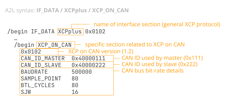
3.1: A2L XCP_ON_CAN (incl. CAN_FD)
Within the IF_DATA XCPplus section we find XCP_ON_CAN. This provides parameter values specific to XCP on CAN (in contrast to e.g. XCP on Ethernet or XCP on FlexRay).
As with other IF_DATA sections, the XCP_ON_CAN keyword is defined in the A2ML schema section. It includes a section called CAN_Parameters, which specifies details like the master/slave CAN IDs and the baud-rate. Note that the structure and naming conventions used in the A2ML section on XCP_ON_CAN are standardized. The specification is detailed in the XCP standard (ASAM MCD-1 XCP) - not in the ASAM MCD-2 MC standard.
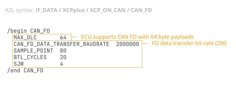
XCP_ON_CAN may also include a CAN_FD keyword if the ECU supports XCP on CAN FD, incl. the max DLC and bit-rate info.
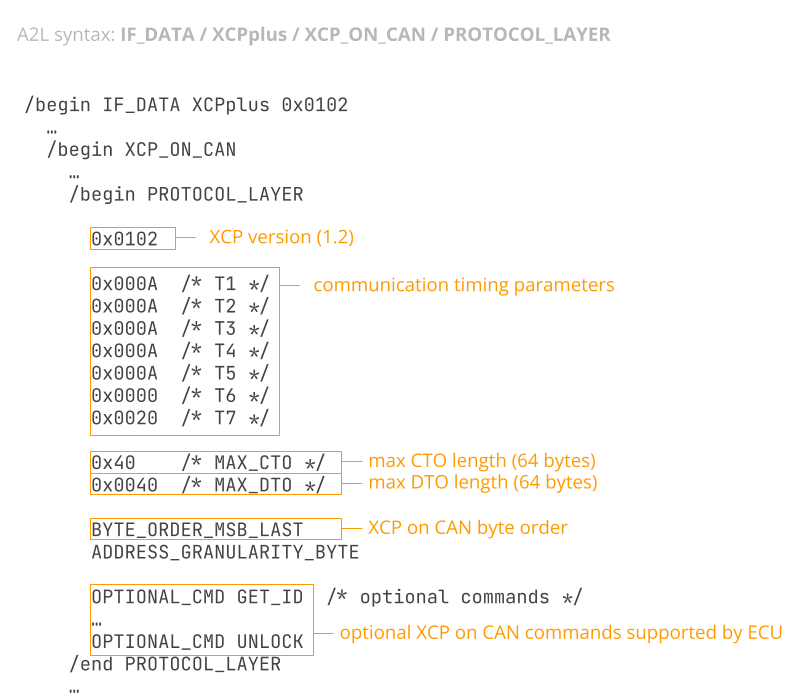
3.2: A2L PROTOCOL_LAYER
As explained, both the XCPplus and nested XCP_ON_CAN sections include the PROTOCOL_LAYER and DAQ sections. Parameter values in XCP_ON_CAN overrule those of XCPplus.
The XCP_ON_CAN PROTOCOL_LAYER section specifies the XCP version (1.2 in this case), MAX_CTO/MAX_DTO values and optional XCP commands supported (e.g. WRITE_DAQ_MULTIPLE). Note how the CTO/DTO values reflect the fact that the ECU supports CAN FD.
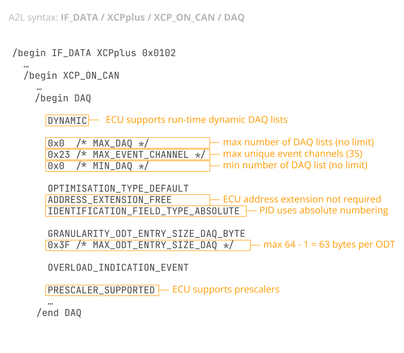
3.3: A2L DAQ
The XCP_ON_CAN DAQ section contains details on Synchronous Data Acquisition in XCP. For example, the sample file specifies that dynamic DAQ lists are supported, that the max ODT entry size is 0x3F (63) bytes - and that prescalers are supported.
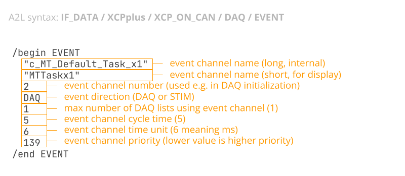
3.4: A2L DAQ / EVENT
The DAQ section also contains EVENT keywords, which reflect event channels that a master tool can use in setting up DAQ lists. Each event contains a name, short name, channel number (used as reference) and direction (DAQ, STIM or both). The EVENT also specifies the number of DAQ lists that may be assigned to the event, the cycle time and unit (e.g. 500 microseconds or 1 millisecond) and the priority (if multiple events compete for ECU resources, lower values are prioritized higher).
How to get the A2L?
A2L files are almost exclusively used by engineers during the development of equipment that incorporates one or more ECUs. Here, the A2L may be provided by the ECU OEM, or it may be created as part of the development process itself. Often, the A2L will be updated throughout the development project to reflect changes to the ECU firmware.
As explained in our intro to CCP/XCP, these protocols are typically disabled once e.g. a vehicle finishes the development process and enters production. Here, other protocols like UDS (Unified Diagnostic Services) are typically used instead.

CANedge: CAN/LIN data logger
The CANedge lets you easily record raw XCP data to an 8-32 GB SD card - or use the CANedge2 / CANedge3 to optionally offload it via WiFi/LTE to your own server. The device can be configured to poll data or use DAQ lists. You can decode the data via free software/APIs.
learn moreA2L software tools (editing & processing)
Software that uses A2L files can be split in two groups: Editing & data processing.
A2L editor tools
As explained in our syntax walkthrough, you can create and edit A2L files with a text editor like Notepad. However, for GUI/API editing, consider below alternatives:
- Vector ASAP2 Studio: This GUI lets you view/edit/create A2L files including a read-only free version. Also supports merging, validation, and comparison of A2L files.
- a2lparser: This open source library lets you parse an A2L file as a Python dictionary for easy scripted search/validation or conversion into formats like JSON or XML.


CCP/XCP data processing tools with A2L/DBC support
Below we outline tools that can be used with the CANedge for enabling CCP/XCP data processing/decoding with the use of A2L and/or DBC files:
- asammdf GUI: The asammdf GUI lets you load raw CCP/XCP on CAN data in MF4 files and decode it via DBC files - as well as create quick plots/exports (more below)
- MF4 decoders: Our MF4 decoders let you DBC decode raw CAN data to create Parquet data lakes - ready for e.g. Grafana dashboards (more below)
- MF4 converters: These let you convert raw CANedge MF4 to enable loading in e.g. Vector CANape for decoding of raw CCP/XCP on CAN communication with A2L files
Note: Below we explain how our canedge-ccp-xcp Python tool lets you easily log and decode XCP on CAN data with the CANedge.
How to log XCP on CAN data based on the A2L?
A popular tool for logging raw CCP/XCP data is the CANedge, which can also offload the data to your own server via WiFi/LTE.
As explained in our intro to CCP/XCP, two options exist for recording internal data from an ECU: Polling and DAQ (Synchronous Data Acquisition).
The CANedge can send custom CAN frames to record CCP/XCP data using either method. In both cases this requires information found in the A2L file as we will explain below.


CANedge configuration file snippet (XCP polling)
Example 1: XCP polling transmit list
To configure the CANedge to poll a list of ECU measurements, you need the below from the A2L (e.g. via a text editor or GUI):
- Master CAN ID (XCP_ON_CAN)
- Byte order (XCP_ON_CAN/PROTOCOL_LAYER)
- ECU addresses (MEASUREMENT)
- Data lengths (based on the data types in MEASUREMENT)
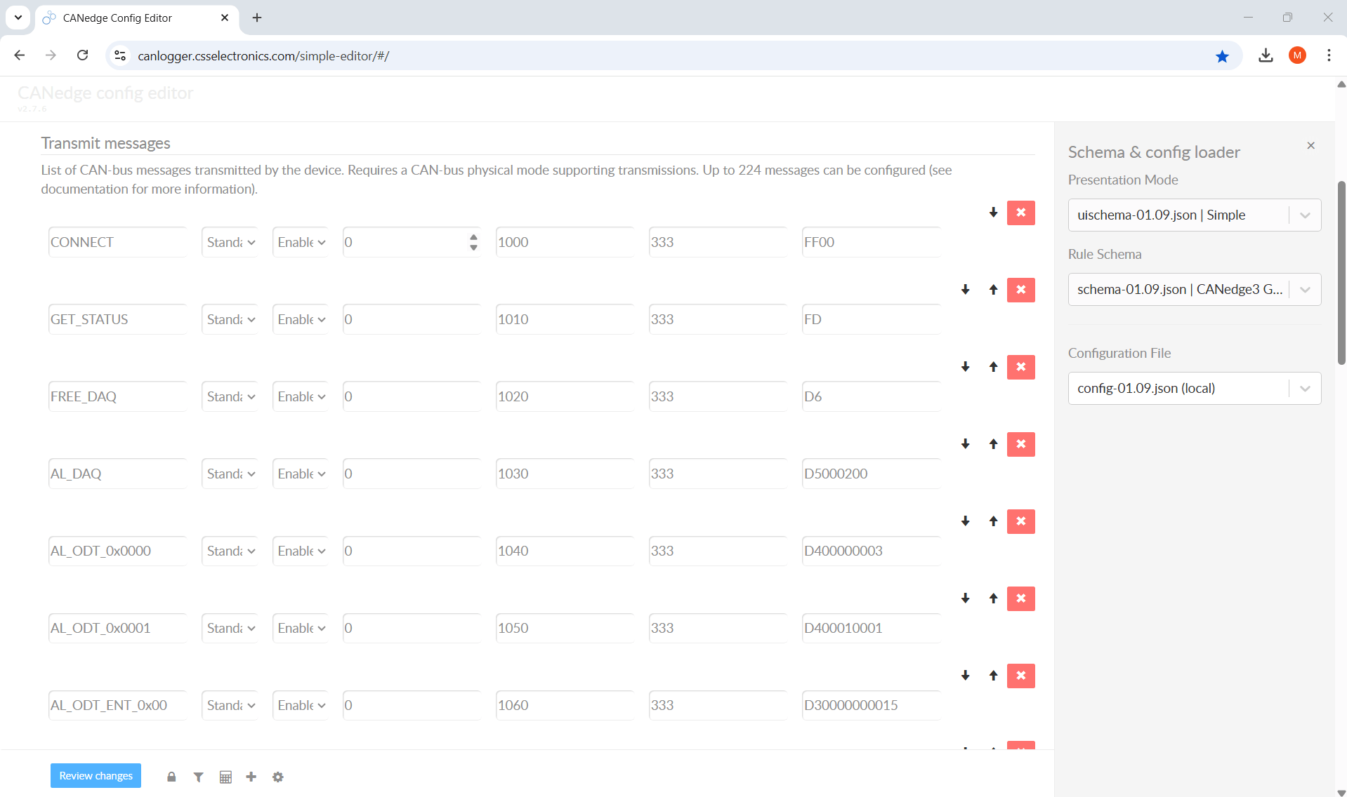
If you extract this from the A2L, you can configure the CANedge transmit list as per the picture to send a periodic polling message for each XCP measurement.
As per our CCP/XCP intro, the 1st data byte is 0xF4, the 2nd is the data length, the 3rd is 0x00 (reserved) and the remaining bytes equal the ECU address (with the byte order specified by the A2L).
Note that you must enable logging of the transmitted frames as the ECU address is not included in the ECU response message - otherwise decoding is not possible.
Example 2: XCP DAQ transmit list
Alternatively, you can configure the CANedge to send a sequence of 'single-shot' CAN frames in order to initialize one or more DAQ lists. Once the DAQ lists are initialized, the CANedge simply records the data with no further transmission required.
To set up DAQ lists, you need the same information as before (master CAN ID, byte order, ECU addresses, data lengths). Further, the user must specify for each measurement what event channel should be used, which will affect how measurements are grouped and broadcast. In addition, you need to determine the following from the XCP_ON_CAN section:
- If CAN FD is supported (CAN_FD)
- Max CTO/DTO length (PROTOCOL_LAYER)
- If WRITE_DAQ_MULTIPLE is supported (PROTOCOL_LAYER)
- Priority of each event channel (DAQ)
With this information you can construct a sequence of frames that will initialize the DAQ lists. In our CCP/XCP intro we provide multiple XCP on CAN DAQ initialization examples.
Constructing DAQ transmit lists manually is impractical. Instead, we recommend using our canedge-ccp-xcp tool, which automates the steps (as outlined below). In the screenshot is an example subset of a resulting DAQ initialization transmit list.
To better understand the logic of how a dynamic DAQ list can be initialized in practice, we provide below a high-level overview of what the canedge-ccp-xcp script does:
- User provides CSV with measurements and event channels
- The script loads the CSV and provided A2L files
- It filters the list to reject any unavailable/invalid
- It groups measurements in DAQ lists based on channel
- Per DAQ, it adds measurements to ODTs (noting MAX_DTO)
- When an ODT is full, the script fills out the next ODT
- Next, it builds the CTO frames (accounting for MAX_CTO)
- These are saved as a JSON transmit list for the CANedge
In building the above, the logic is to first compose the DAQ-DTO frames by determining how measurements should be grouped in terms of DAQ lists (depending on event channel) and ODT lists. As an example, the user may want to measure 5 measurements with event channel 2. This results in a single DAQ list to match the event channel. The script determines from the A2L that the measurements all have a length of 2 bytes and that the MAX_DTO is 8. Each DAQ-DTO uses the 1st byte for the PID, leaving in this case 7 bytes for packaging signals. The script can therefore package floor(7 / 2) = 3 measurements in the first ODT and the remaining 2 in the next ODT. Of course, if the MAX_DTO is 64, all 5 measurements could fit within a single ODT and thus only one DAQ-DTO frame would be required.
As for constructing the required CTO frames, the script first adds some static frames (e.g. the XCP CONNECT frame). After this, it starts adding the required CTO command frames e.g. FREE_DAQ, ALLOC_DAQ, ALLOC_ODT, ALLOC_ODT_ENTRY, SET_DAQ_PTR, WRITE_DAQ etc. The details of how these commands are created match the various XCP DAQ initialization examples shown in our intro to CCP/XCP and depend on the previous grouping logic, as well as the MAX_CTO. If the MAX_CTO is 8, regular Classical CAN frames are used for the initialization. If MAX_CTO is 64 and WRITE_DAQ_MULTIPLE is supported according to the A2L file, then the initialization can be made much more efficient by leveraging CAN FD.
It should be noted that some ECUs may restrict access to setting up DAQ lists by requiring that a seed & key authentication is performed between the master tool and ECU, see also our intro to CCP/XCP.
In practice, however, many OEMs disable the seed & key authentication entirely - and if it is enabled, it often only restricts stimulation (STIM) or programming (PGM), rather than DAQ.
The CANedge does not support seed & key authentication, so if you need to use it for XCP on CAN data logging, we recommend to check if authentication is enabled or not (via the GET_STATUS command). If it is enabled, you may be able to disable it on the ECU you wish to record from. If not, you can consider to use polling as a fall back (as this cannot be restricted by authentication).
 CANedge configuration file snippet (XCP DAQ)
One step in generating a dynamic DAQ initialization sequence is to group measurements into DAQ and ODT lists (extract from our canedge-ccp-xcp tool)

How to decode XCP on CAN data using an A2L/DBC file?
As explained, the CANedge can be configured to record data via polling or DAQ. Similarly, you can decode the raw data into physical values based on the A2L, though the method depends on your data acquisition method and software/API tool.
Example 1: Decoding XCP polling data
If you record ECU data via polling, you can decode the data into physical values if you have both the request (with the ECU address) and the response (with the actual data).
To decode the data using your A2L file directly, you can use our MF4 converters to 'finalize' your log file into a sorted & finalized MF4 (for loading in e.g. Vector CANape), which will allow you to also load your A2L and decode the data directly.
If you want to use other tools (e.g. asammdf) to decode your polling data, there are some challenges involved, however. As explained in our intro to CCP/XCP, the ECU sends different ECU measurements using the same slave CAN ID - with no way to distinguish them in the payload. In other words, you need to 'combine' the request and response frame so that you can use the ECU address as a multiplexor. This is not directly supported in any CANedge software/API tools without custom scripting.
Conclusion: You should only use CCP/XCP polling with the CANedge if your end goal is to decode the data within software tools like Vector CANape. Otherwise use DAQ lists instead.
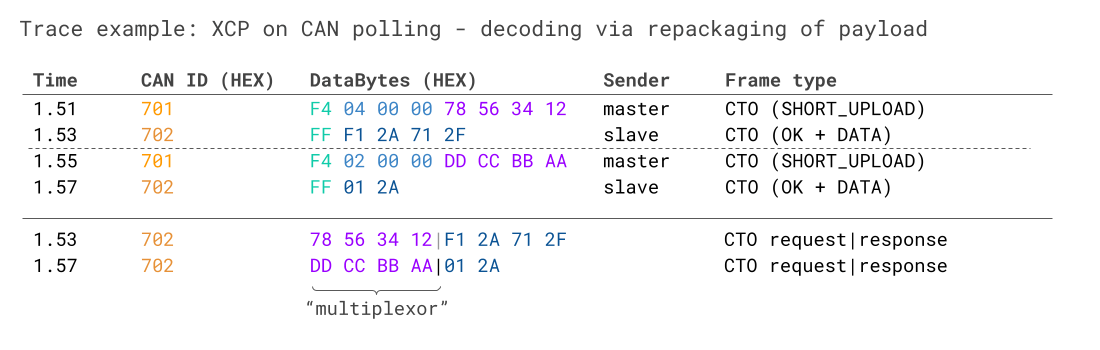 This example illustrates the challenge of how polled data requires XCP frame
assembly, which
most general-purpose CAN software/API tools do not support
This example illustrates the challenge of how polled data requires XCP frame
assembly, which
most general-purpose CAN software/API tools do not support
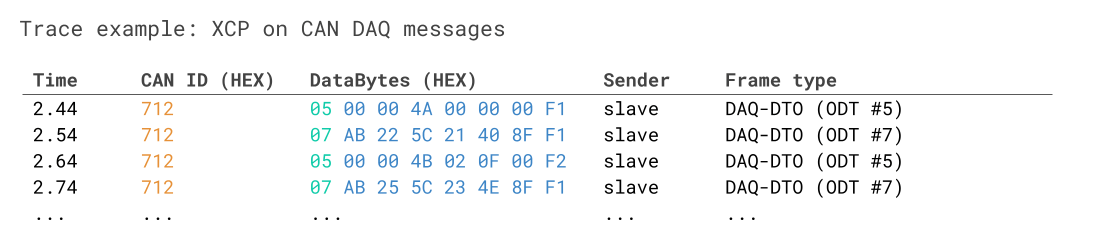 DAQ-DTOs can be easily decoded with standard CAN bus software/API tools by
leveraging the PID as a multiplexor
DAQ-DTOs can be easily decoded with standard CAN bus software/API tools by
leveraging the PID as a multiplexor
Example 2: Decoding XCP DAQ data
As evident, decoding polling data is complex.
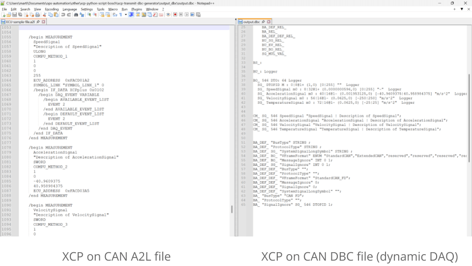
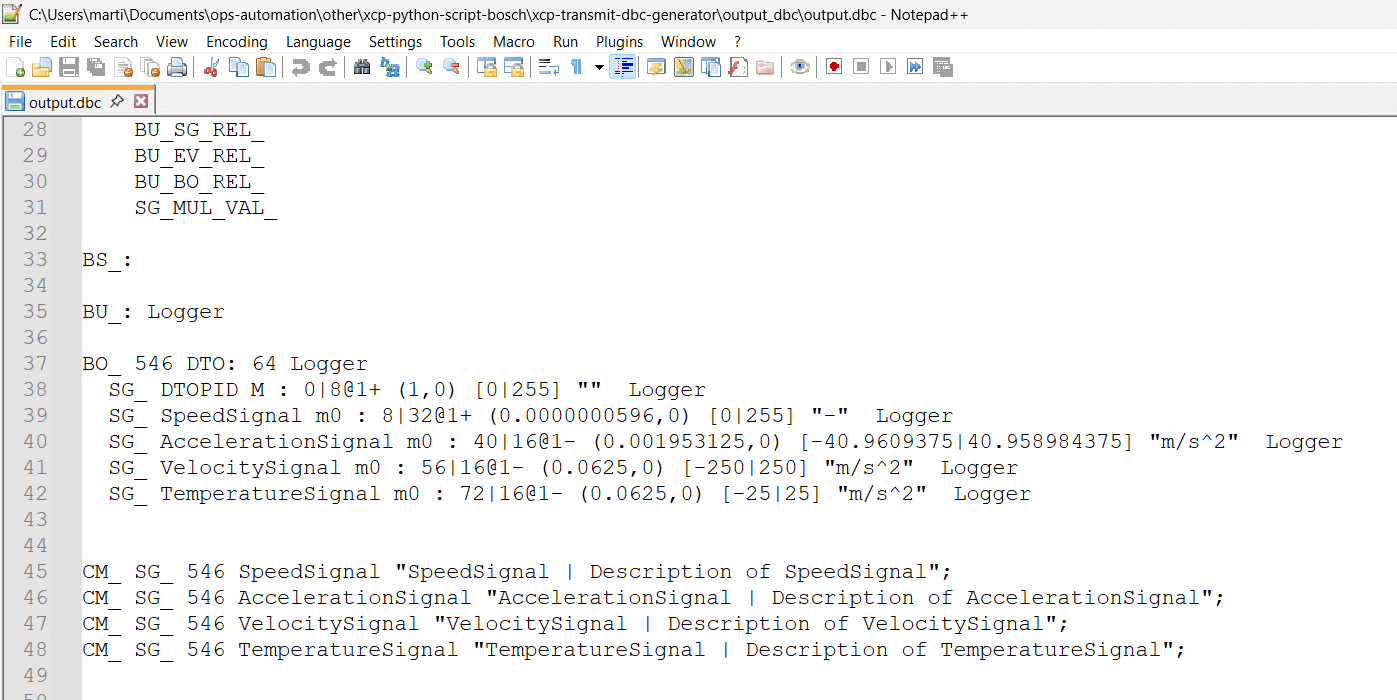
However, decoding DAQ data is much simpler. You can of course use Vector CANape as before, but decoding can now also be done via DBC files in most CAN software/API tools.
This is because each DAQ-DTO frame can be uniquely distinguished via the 1st byte (the packet identifier or PID), which reflects an Object Descriptor Table (ODT) number. This means that a DBC file can be created that uses the DAQ-DTO PID as a multiplexor to apply separate decoding rules depending on its value - without performing any multi-frame assembly. This makes it very similar to DBC files for OBD2 data.
To build a DBC for XCP on CAN DAQ, we need below info:
- ID (the slave CAN ID from XCP_ON_CAN)
- Message name (can be generic and e.g. set to DTO)
- Signal name (i.e. measurement name, capped at 32 chars)
- Start bit (start bit of the measurement in the payload)
- Length (length of the measurement based on the data type)
- Endianness (byte order from XCP_ON_CAN/PROTOCOL_LAYER)
- Scale (how to multiply the measurement value)
- Offset (how to offset the measurement value)
- Signage (measurement signage based on the data type)
- Unit/min/max (extra info from the measurement section)
As evident, most of this is simple to extract from the A2L, including the slave CAN ID, name, length, endianness, signage, unit/min/max - all of which we covered before.
However, some properties are more complex:
2.1 Identify scale/offset
As per the syntax section, A2L files describe conversion methods separately from measurements (in contrast to DBC files).
As a result, we need to first map each measurement to a conversion method using the COMPU_METHOD reference.
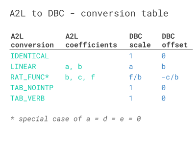
Next, we need to filter the conversion methods to the subset supported by DBC files. Luckily, this includes most methods, incl. IDENTICAL, LINEAR, RAT_FUNC (when a = d = e = 0). It can also encompass TAB_NOINTP and TAB_VERB via the use of DBC value tables. In particular, DBC files support linear scaling of signals as below:
The A2L to DBC table shows how COMPU_METHOD coefficients can be mapped to the DBC scale and offset.
2.2 Identify start bit and multiplexor value
To determine the start bit and multiplexor value of each measurement, we need to review the way the measurements are grouped into DAQ lists and ODT lists, as well as the order in which the measurements are added within each ODT.
This information can be extracted during the process in which we construct the DAQ-DTO frames (as explained in the transmit section). From this, we know the ODT number (and hence PID value aka multiplexor value) for each measurement. Based on the ordering of the measurements within the ODT and their data lengths, we can determine the start bit of each measurement.
 DBC files support using the DAQ-DTO PID as a multiplexor to distinguish ODTs and
thus signal decoding rules
DBC files support using the DAQ-DTO PID as a multiplexor to distinguish ODTs and
thus signal decoding rules
In conclusion, it is possible to construct a DBC that enables easy, tool-agnostic decoding of DAQ-DTOs via multiplexing. This solidifies DAQ as the superior method for XCP data acquisition via the CANedge.

canedge-ccp-xcp Python tool
Need to log, decode and analyze CCP/XCP data?
Our 100% open source canedge-ccp-xcp tool makes it easy to deploy the CANedge for CCP or XCP on CAN data logging using dynamic DAQ lists. The tool lets you provide your A2L and a CSV with your requested measurements and event channels. Using this, the tool auto-generates a CANedge transmit list and DBC file. The tool supports CAN FD incl. the WRITE_DAQ_MULTIPLE command.
This tool lets you easily log your ECU data with the CANedge and analyze it with e.g. the asammdf GUI, Grafana dashboards, python-can, Vector tools, MATLAB and more.
The tool also provides functionality for adding the DAQ transmit list to an existing CANedge Configuration File (and validating it), as well as creating transmit lists for multi-ECU communication.
Today, the canedge-ccp-xcp tool is actively used by OEM engineers for CCP and XCP data acquisition in prototype vehicles.
If you have questions on using the tool, contact us.
canedge-ccp-xcp github pageReady to log your CCP/XCP data?
Get your CANedge today!


