J1939 Explained - A Simple Intro [2023]
Need a simple, practical intro to SAE J1939?
In this guide we introduce the J1939 protocol basics incl. PGNs and SPNs.
Note: This is a practical intro so you will also learn how to decode J1939 data via DBC files, how J1939 logging works, key use cases and practical tips.
Learn below why this has become the #1 introduction to J1939.
You can also watch our J1939 intro above - or get the PDF

What is J1939?
In short, SAE J1939 is a set of standards that define how ECUs communicate via the CAN bus in heavy-duty vehicles.
As explained in our CAN bus intro, most vehicles today use the Controller Area Network (CAN) for ECU communication. However, CAN bus only provides a "basis" for communication (like a telephone) - not a "language" for conversation.
In most heavy-duty vehicles, this language is the SAE J1939 standard defined by the Society of Automotive Engineers (SAE).
In more technical terms, J1939 provides a higher layer protocol (HLP) based on CAN as the "physical layer".
What does that mean, though?


One standard across heavy-duty vehicles
In simple terms, J1939 offers a standardized method for communication across ECUs, or in other words:
J1939 provides a common language across manufacturers.
In contrast, e.g. cars use proprietary OEM specific protocols.
Heavy-duty vehicles (e.g. trucks and buses) is one of the most well-known applications. However, several other key industries leverage SAE J1939 today either directly or via derived standards (e.g. ISO 11783, MilCAN, NMEA 2000, FMS):
- Foresting machines (e.g. delimbers, forwarders, skidders)
- Mining vehicles (e.g. bulldozers, draglines, excavators, …)
- Military vehicles (e.g. tanks, transport vehicles, …)
- Agriculture (e.g. tractors, harvesters, …)
- Construction (e.g. mobile hydraulics, cranes, …)
- Fire & Rescue (e.g. ambulances, fire trucks, …)
- Other (e.g. ships, pumping, e-buses, power generation, ...)
The standardization is a key enabler to data logging use cases across heavy-duty vehicles - more on this further below.
J1939 history


J1939 future
With the rise of heavy-duty telematics, J1939 will increasingly play a role in the market for connected vehicles. In turn, this will increase the need for secure J1939 IoT loggers.
In parallel, OEMs will increasingly shift from Classical CAN to CAN FD as part of the transition to J1939 with flexible data-rate. In turn, this will increase the need for J1939 FD data loggers.
"The market for in-vehicle connectivity - the hardware and services bringing all kinds of new functionality to drivers and fleet owners - is expected to reach EUR 120 billion by 2020."
- Boston Consulting Group, Connected Vehicles and the Road to Revenue
4 key characteristics of J1939
The J1939 protocol has a set of defining characteristics outlined below:

250K baud rate &
29-bit extended ID
The J1939 baud rate is typically 250K (though recently with support for 500K) - and the identifier is extended 29-bit (CAN 2.0B)

Broadcast + on-request data
Most J1939 messages are broadcast on the CAN-bus, though some data is only available by requesting the data via the CAN bus

PGN identifiers & SPN parameters
J1939 messages are identified by 18-bit Parameter Group Numbers (PGN), while J1939 signals are called Suspect Parameter Numbers (SPN)

Multibyte variables & Multi-packets
Multibyte variables are sent least significant byte first (Intel byte order). PGNs with up to 1785 bytes are supported via J1939 transport protocol
Below are a set of additional characteristics of the J1939 protocol:
- Reserved: J1939 includes a large range of standard PGNs, though PGNs 00FF00 through 00FFFF are reserved for proprietary use
- Special Values: A data byte of 0xFF (255) reflects N/A data, while 0xFE (254) reflects an error
- J1939 address claim: The SAE J1939 standard defines a procedure for assigning source addresses to J1939 ECUs after network initialization via an 8-bit address in a dynamic way
J1939 is based on CAN, which provides the basic "physical layer" and "data link layer", the lowest layers in the OSI model.
Basically, CAN allows the communication of small packets on the CAN bus, but not a lot more than that. Here, J1939 serves as a higher layer protocol on top, enabling more complex communication.
A higher layer protocol enables communication across the large complex networks of e.g. vehicle manufacturers.
For example, the SAE J1939 protocol specifies how to handle "multi-packet messages", i.e. when data larger than 8 bytes needs to be transferred. Similarly, it specifies how data is to be converted into human-readable data.
It does so by providing a family of standards. For example, J1939-71 is a document detailing the information required to convert a large set of cross-manufacturer standardized J1939 messages into human-readable data (more on this below).
Many other CAN based higher layer protocols exist, e.g. CANopen, DeviceNet, Unified Diagnostic Services. These typically offer some level of standardization within their respective industries - though all of them can be extended by manufacturers.
In comparison, the aforementioned passenger cars have unique standards per manufacturer. In other words, you can use the same J1939 database file to convert e.g. engine speed across two trucks from different manufacturers - but you cannot e.g. read the data from an Audi A4 using the same IDs & scaling parameters as for a Peugeot 207.

The J1939 connector (9-pin)
The J1939-13 standard specifies the 'off-board diagnostic connector' - also known as the J1939 connector or 9-pin deutsch connector. This is a standardized method for interfacing with the J1939 network of most heavy duty vehicles - see the illustration for the J1939 connector pinout.
Note that the J1939 deutsch connector comes in two variants: The original black connector (type 1) and the newer green connector (type 2), which started getting rolled out around 2013-14.
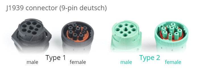
J1939 type 2 female connectors are physically backwards compatible, while type 1 female connectors only fit type 1 male sockets. The type 2 connector was designed for the SAE J1939-14 standard, which adds support for 500K bit rates. The purpose of "blocking" type 1 connectors is to ensure that older hardware (presumably using 250K bit rates) is not connected to type 2 500K bit rate J1939 networks. Specifically, the physical block is through a smaller hole for pin F in the type 2 male connectors.
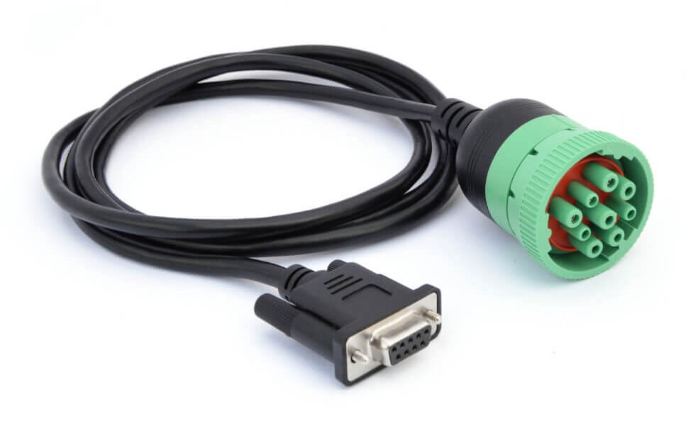
Below is an example of a DB9-J1939 adapter cable (type 2):
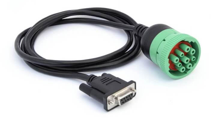
As evident, the J1939 deutsch connector provides access to the J1939 network through pins C (CAN high) and D (CAN low). This makes it easy to interface with the J1939 network across most heavy duty vehicles.
In some cases, however, you may also be able to access a secondary J1939 network through pins F and G or pins H and J (with H being CAN H and J being CAN L).
Many of today's heavy duty vehicles have 2 or more parallel CAN bus networks and in some cases at least two of these will be available through the same J1939 connector. This also means that you will not necessarily have gained access to all the available J1939 data if you've only attempted to interface through the 'standard' pins C and D.
While the J1939 deutsch connector is the most common way to interface with the J1939 network of heavy duty vehicles, other connectors of course exist. Below are some examples:
- J1939 Backbone Connector: This 3-pin deutsch connector provides pins for CAN H/L a CAN shield (no power/ground)
- CAT connector: The Caterpillar industrial connector is a grey 9-pin deutsch connector. However, the pin-out differs from the J1939 connector (A: Power, B: Ground, F: CAN L, G: CAN H) and the connector physically blocks access from standard type 1 and 2 J1939 connectors
- OBD2 type B connector: The type B OBD2 connector (SAE J1962) in heavy duty vehicles sometimes provide direct access to the J1939 network through pins 6 and 14
- Volvo 2013 OBD2 connector: This variant matches the type B OBD2 connector, but also adds access to the J1939 high via pin 3 and J1939 low via pin 11

The J1939 PGN and SPN
In the following section we explain the J1939 PGNs and SPNs.
Parameter Group Number (PGN)
The J1939 PGN comprises an 18-bit subset of the 29-bit extended CAN ID. In simple terms, the PGN serves as a unique frame identifier within the J1939 standard. For example, you can look this up in the J1939-71 standard documentation, which lists PGNs/SPNs.

Assume you recorded a J1939 message with HEX ID 0CF00401.
Here, the PGN starts at bit 9, with length 18 (indexed from 1).
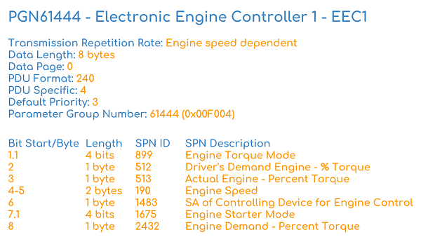
The resulting PGN is 0F004 or in decimal 61444. Looking this up in the SAE J1939-71 documentation, you will find that it is the "Electronic Engine Controller 1 - EEC1".
Further, the document will have details on the PGN including priority, transmission rate and a list of the associated SPNs - cf. the illustration.
For this PGN, there are seven SPNs (e.g. Engine Speed, RPM), each of which can be looked up in the J1939-71 documentation for further details.

Detailed breakdown of the J1939 PGN
Let's look at the CAN ID to PGN transition in detail.
Specifically, the 29 bit CAN ID comprises the Priority (3 bits), the J1939 PGN (18 bits) and the Source Address (8 bits). In turn, the PGN can be split into the Reserved Bit (1 bit), Data Page (1 bit), PDU format (8 bit) and PDU Specific (8 bit).
The detailed PGN illustration also includes example values for each field in binary, decimal and hexadecimal form.
To learn more about the transition from 29 bit CAN ID to 18 bit J1939 PGN, see also our online CAN ID to J1939 PGN converter. The converter also includes a full J1939 PGN list for PGNs included in our J1939 DBC file.
Suspect Parameter Number (SPN)
The J1939 SPN serves as the identifier for the CAN signals (parameters) contained in the databytes. SPNs are grouped by PGNs and can be described in terms of their bit start position, bit length, scale, offset and unit - information required to extract and scale the SPN data to physical values.

Assume you have recorded a raw J1939 frame as below:
| CAN ID | Data bytes |
| 0CF00401 | FF FF FF 68 13 FF FF FF |
By converting the CAN ID to the J1939 PGN you identify that this is the PGN 61444 from before. From the J1939-71 document, you observe that one of the SPNs within this PGN is Engine Speed (SPN 190) with details as in the illustration below.
Using these details, it is possible to extract the Engine Speed physical value data e.g. for plot purposes. To do so, note from the SPN info that the relevant data is in bytes 4 and 5, i.e. the HEX data bytes 68 and 13. Taking the decimal form of the HEX value 1368 (Intel byte order), we get 4968 in decimal. To arrive at the RPM, we conduct a scaling of this value using the offset 0 and the scale 0.125 RPM/bit.
The physical value (aka scaled engineering value) is 621 RPM.
Note how some data bytes in the above are FF or 255 decimal, i.e. not available. While the PGN may theoretically support SPNs in this range, the FF padding means that this particular application does not support these parameters.

In practice, you will not PDF-lookup decoding rules for J1939 data - instead, this info can be stored in a CAN database file (DBC).
Example: J1939 DBC file
A J1939 DBC file can be used to decode data across most heavy-duty vehicles. For example, raw J1939 data can be recorded with a CAN bus data logger and analyzed in a CAN software tool that supports DBC conversion (e.g. asammdf).
This will typically result in a conversion of 40-60% of the vehicle data - with the rest being OEM specific proprietary data that requires reverse engineering.
j1939 dbc intro
J1939 truck sample data: Raw & physical values
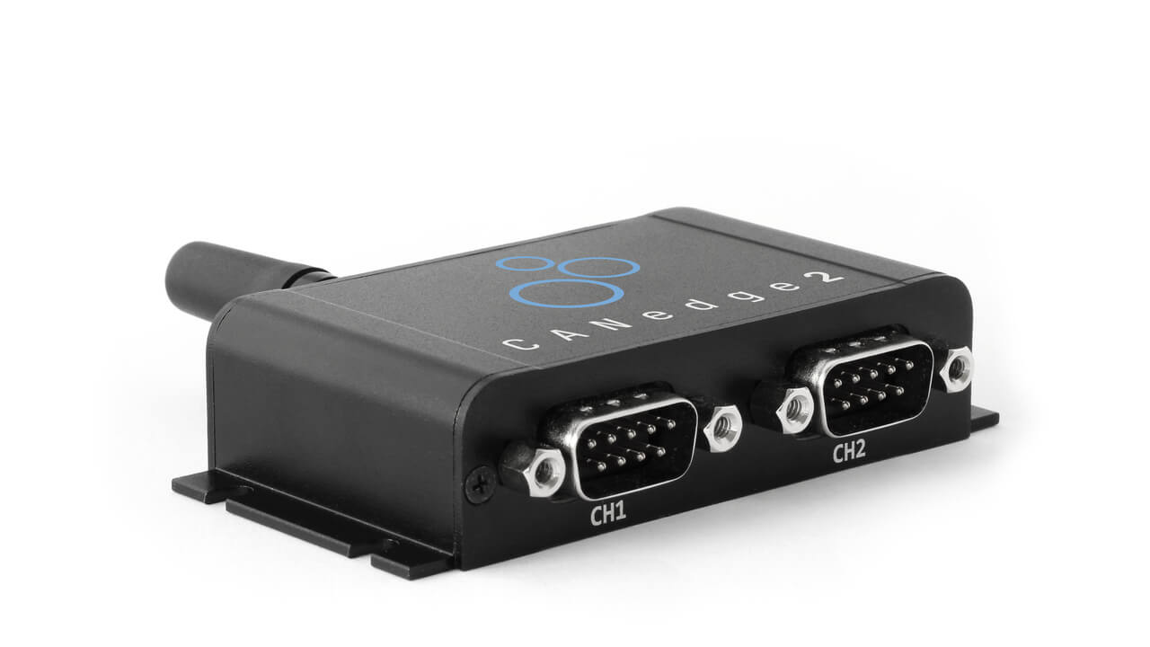
Below we illustrate what real J1939 data looks like. The 'raw' J1939 data was recorded from a heavy duty truck using a CANedge2, while the 'physical values' reflect the output after decoding the raw data via the free asammdf software and the J1939 DBC.
Data from the CANedge is recorded in a standardized binary format, MDF4, which can be converted to any file format via our MDF4 converters (e.g. to CSV, ASC, TRC, ...). Below is a CSV version of the raw J1939 frames. Notice that the CAN IDs and data bytes are in hexadecimal format:
You can optionally download full raw J1939 MDF4 samples from the CANedge2 in our intro docs. The sample data also includes a demo J1939 DBC so that you can replicate the conversion steps via asammdf.
Once the raw J1939 data is decoded and exported, the result is timeseries data with parameters like oil temperature, engine speed, GPS, fuel rate and speed:
For more on logging J1939 data, see our J1939 data logger and mining telematics articles.
About the CANedge J1939 logger
The CANedge lets you easily record J1939 data to an 8-32 GB SD card. Simply connect it to e.g. a truck to start logging - and decode the data via free software/APIs and our J1939 DBC.
j1939 logger introJ1939 request messages
Most J1939 messages are broadcast via the CAN bus, but some are only sent "on-request" (e.g. when polled by a J1939 data logger).
On-request data often includes J1939 diagnostic trouble codes (DTCs), making it important in J1939 diagnostics - see also our J1939-73 DBC file. Below we briefly outline how it works:

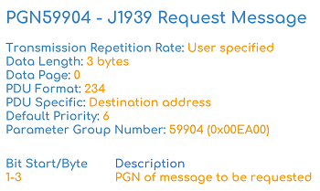
To send a J1939 request via the CAN bus, a special 'request message' is used (PGN 59904), which is the only J1939 message with only 3 bytes of data. It has priority 6, a variable transmit rate and can either be sent as a global or specific address request. The data bytes 1-3 should contain the requested PGN (Intel byte order). Examples of requested J1939 messages include the diagnostic messages (e.g. J1939 DM2).
A CAN bus data logger like the CANedge can be set up to send J1939 request messages - see e.g. our CANedge Intro for a detailed step-by-step guide.
J1939 code requests vs warranty compliance
Sending request messages is typically key to requesting J1939 codes and thus J1939 diagnostics. One challenge, however, is that J1939 loggers are often required to have a contactless connection to the J1939 data link, meaning that they're unable to interact with the CAN bus and transmit J1939 request frames. The restriction is often related to warranty compliance as some vehicle manufacturers do not allow direct access by 3rd party devices via the J1939 connector.
In some cases, it is required that the J1939 analyzer is "physically" contactless, e.g. via a CANcrocodile adapter. In other cases, it is sufficient that the J1939 logger operates in "configurable" silent mode. The latter makes it easier to perform ad hoc requests for J1939 fault codes, either via a manual configuration update or via an over-the-air update for the CANedge2.
 A J1939 connector allows direct access to the CAN bus
J1939 transport protocol (TP)
The previous PGN and SPN examples are based on J1939 messages with 8 data bytes. While these are most common, J1939 multi-frame messages also exist with >8 data bytes - sent via the J1939 transport protocol.
Below we outline how the J1939 transport protocol works, a practical J1939 TP data example and how to decode multi-frame J1939 messages via DBC files:

The J1939 protocol specifies how to deconstruct, transfer and reassemble packets across multiple frames - a process referred to as the J1939 Transport Protocol (see J1939-21). Two types of the J1939 TP exist:
- The Connection Mode (intended for a specific device)
- The BAM (Broadcast Announce Message) which is intended for the entire network
For example, a transmitting ECU may send an initial BAM packet to set up a data transfer. The BAM specifies the PGN identifier for the multi-packet message as well as the number of data bytes and packets to be sent. It is then followed by up to 255 packets/frames of data. Each of the 255 packets use the first data byte to specify the sequence number (1 up to 255), followed by 7 bytes of data. The max number of bytes per multi-packet message is therefore 7 bytes x 255 = 1785 bytes.
The final packet contains at least one byte of data, followed by unused bytes set to FF. In the BAM type scenario, the time between messages is 50-200 ms. In post processing, a conversion software tool can reassemble the multiple entries of 7 data bytes into a single payload and handle it according to the multi-packet PGN and SPN specifications as found in e.g. a J1939 DBC file.
Decoding J1939 multiframe data is more complex than decoding standard J1939 frames. To understand why, consider the below example of a J1939 transport protocol response, recorded with the CANedge2:
The above sequence consists of two J1939 message types:
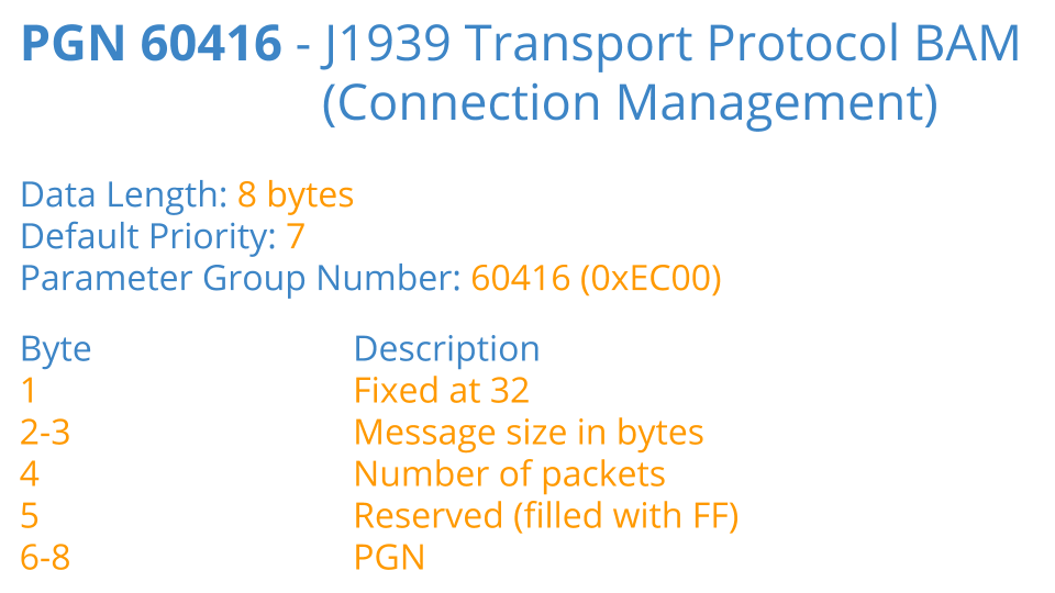
A J1939 BAM message with ID 1CECFF00 (PGN 60416 or EC00). This contains the response data length and J1939 PGN
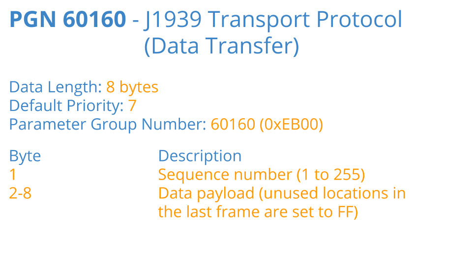
A J1939 data transfer messages with ID 1CEBFF00 (PGN 60160 or EB00). These contain the payload across multiple frames
Below we break down the J1939 transport protocol example with focus on the data byte interpretation:
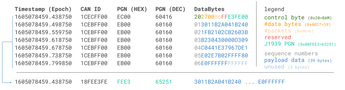
Generally, a J1939 transport protocol response sequence can be processed as follows:
- Identify the BAM frame, indicating a new sequence being initiated (via the PGN 60416)
- Extract the J1939 PGN from bytes 6-8 of the BAM payload to use as the identifier of the new frame
- Construct the new data payload by concatenating bytes 2-8 of the data transfer frames (i.e. excl. the 1st byte)
Above, the last 3 bytes of the BAM equal E3FE00. When reordered, these equal the PGN FEE3 aka Engine Configuration 1 (EC1). Further, the payload is found by combining the the first 39 bytes across the 6 data transfer packets/frames.
Note: The last 3 data payload bytes in this practical example happen to be FF, yet we still include these in the payload as the BAM message specifies the data length to be 39. The final 3 FF bytes in the 6th packet are unused.
With the method explained above, we have created a 'constructed' J1939 data frame with a data length exceeding 8 bytes. This frame can be decoded using a J1939 DBC file, just like a regular J1939 data frame. For the PGN EC1, the J1939 DBC specifies a data length of 40 with signals defined for the full payload.
As such, once the J1939 software/API has reconstructed the multiframe response into a single J1939 frame, the DBC decoding can be done as usual. One minor tweak is that most J1939 DBC files expects that the raw log file of J1939 data will contain 29-bit CAN IDs (not 18-bit J1939 PGNs). As such, if the software embeds the reconstructed J1939 TP frame in the original raw data, it may need to convert the extracted J1939 PGN into a 29-bit CAN ID first. You can also see our J1939 PGN converter, which breaks down how a J1939 PGN can be converted to a 29-bit CAN ID.
J1939 TP data & Python API decoding
The CANedge lets you request and record J1939 transport protocol data. To decode the TP data, you can either convert the raw log files to another format (like Vector ASC), or you can use our Python API. In our api-examples library on github, we provide a basic example of how J1939 transport protocol data can be reconstructed and DBC decoded, incl. sample data.
Since the CANedge Python API enables decoding of J1939 transport protocol data, J1939 signals from multiframe messages can e.g. be visualized in J1939 telematics dashboards.
api examples telematics dashboards CANedge softwareLogging J1939 data - example use cases
There are several common use cases for recording J1939 data:

Heavy duty fleet telematics
J1939 data from trucks, buses, tractors etc. can be used in fleet management to reduce costs or improve safety
j1939 telematics
Live stream diagnostics
By streaming decoded J1939 data to a PC, technicians can perform real-time J1939 diagnostics on vehicles
j1939 streaming
Predictive maintenance
Vehicles can be monitored via WiFi CAN loggers in the cloud to predict breakdowns based on the J1939 data
predictive maintenance
Heavy-duty vehicle blackbox
A CAN logger can serve as a 'blackbox' for heavy-duty vehicles, providing data for e.g. disputes or J1939 diagnostics
can bus blackboxDo you have a J1939 data logging use case? Reach out for free sparring!
Contact us6 practical tips for J1939 data logging
Many of our end users work with J1939 logging in the field - and below we share 6 practical logging tips:
Standalone J1939 data loggers with SD cards are ideal for logging data from e.g. vehicle fleets over weeks or months. A WiFi J1939 logger also enables telematics use cases. In contrast, a J1939 USB-PC interface requires a PC to stream data from the CAN bus in real-time. This is e.g. useful for diagnostic purposes - or analysing physical events. The CLX000 enables both modes of operation, while the CANedge2 is perfect for telematics.
To connect your CAN analyzer to a J1939 asset (e.g. a truck) you can typically use the 9-pin J1939 connector. We offer a DB9-J1939 adapter which fits the 9-pin deutsch connector found in many heavy duty vehicles. Alternatively, you may prefer to connect your CAN logger directly to the CAN bus via e.g. a CANCrocodile. This method uses induction to record data silently without cutting any CAN wiring.
For vehicle fleet management & telematics you will typically upload the data via either WiFi or 3G/4G. The CANedge2 enables WiFi data transfer, which is ideal if you have an existing WiFi router available in the vehicle (e.g. for some transit buses, trains, tractors) or if the vehicle frequently returns to the same WiFi network in e.g. a garage. If no WiFi is available, the CANedge3 offers built-in 3G/4G connectivity instead of WiFi. Simply insert your own SIM card to allow the device to upload data from your heavy duty assets while on-the-road.
When logging or streaming J1939 data, software for post processing is key. In particular, the software should support DBC-based J1939 conversion to allow easy conversion to human-readable data. The free supporting softwares/APIs for our CAN loggers support this. For USB streaming, our free SavvyCAN plugin enables live DBC conversion. Further, we offer a digital download J1939 DBC file in collaboration with SAE.
Some J1939 PGNs are only available on-request, meaning that you need to "poll" the CAN bus to log these. The CANedge and CLX000 are able to transmit custom CAN messages, which can be used to send periodic PGN requests. Note that this is not possible in "silent mode" (i.e. it is not possible if the logger is connected via e.g. a CANCrocodile).
To optimize your J1939 data logging, a number of advanced configurations can be helpful. In particular, the CANedge advanced filters and sampling rate options help optimize the amount of data logged - key for e.g. minimizing cellular bandwidth usage. Other options include silent mode and cyclical logging, with the latter enabling the logger to always prioritize the latest data (useful in e.g. blackbox logging).
Since J1939 is standardized, it is critical to encrypt your data 'at rest' (e.g. on an SD card) and 'in transit' (during upload). Not doing so exposes your data processing to various security risks, incl. GDPR/CCPA fines and loss of confidentiality and data integrity. For details on securing your J1939 data logging, see our intro to secure CAN logging.
For more intros, see our guides section - or download the 'Ultimate Guide' PDF.
Need to log/stream J1939 data?
Get your CAN logger today!